Thread: 55 Wagon Progress
-
05-13-2021 07:46 AM #1621
A very nice show with a top notch cars, wagons & trucks! Cody's metal work is amazing!
I had trouble with which woody was the Willys, but finally blew up the image of the brown one (last woody shown) to read the logo on the side of the hood. The grille is a bit different from any Willys I've seen, and there are several really nice woody's there! Finally found a picture of a mint green one that ID'd it as a '40! Very nice!Last edited by rspears; 05-13-2021 at 08:06 AM.
Roger
Enjoy the little things in life, and you may look back one day and realize that they were really the BIG things.
-
Advertising

- Google Adsense
- REGISTERED USERS DO NOT SEE THIS AD
-
05-14-2021 04:53 AM #1622
That black '36 roadster has a familiar look to it..........hmmmmmYour Uncle Bob, Senior Geezer Curmudgeon
It's much easier to promise someone a "free" ride on the wagon than to urge them to pull it.
Luck occurs when preparation and opportunity converge.
-
05-14-2021 05:44 AM #1623
Belongs to Mabe Pouncy, actually is a green color off a new AMG Mercedes.Robert
-
05-14-2021 09:00 AM #1624
Robert, I was thinking of this one once owned by a far less famous guy.
Your Uncle Bob, Senior Geezer Curmudgeon
It's much easier to promise someone a "free" ride on the wagon than to urge them to pull it.
Luck occurs when preparation and opportunity converge.
-
05-14-2021 09:24 AM #1625
I could be wrong Bob but wasn't yours a deep blue?
Jack.www.clubhotrod.com/forums/showthread.php?t=44081
-
05-15-2021 04:51 AM #1626
Good to see ya Jack. Yes, you'd be wrong..................
Your Uncle Bob, Senior Geezer Curmudgeon
It's much easier to promise someone a "free" ride on the wagon than to urge them to pull it.
Luck occurs when preparation and opportunity converge.
-
06-22-2021 07:50 AM #1627
Well after about two months of travel for the day job, hangin TV's....
https://youtu.be/Kw1LEhtzkP8
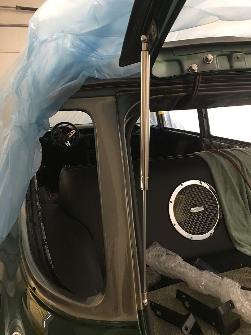
…..we finally got back to work on the wagon and some long overdue progress. The lift gate has been outfitted with some stainless prop rods...
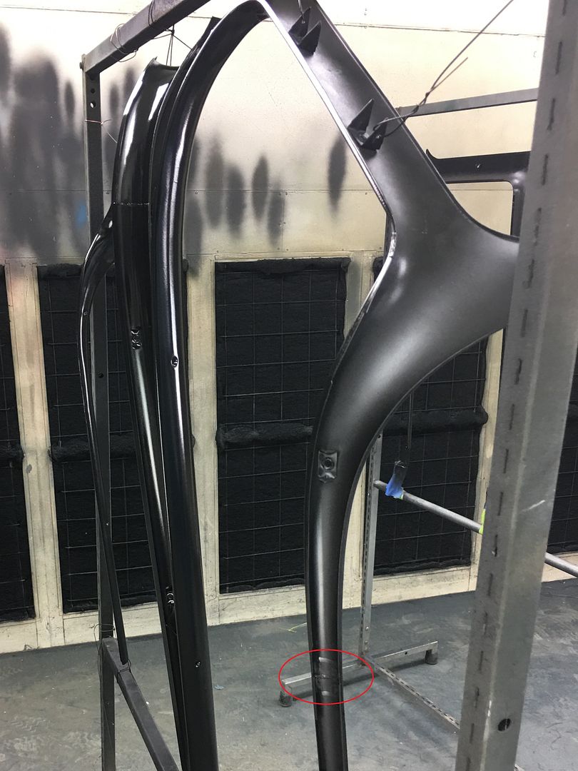
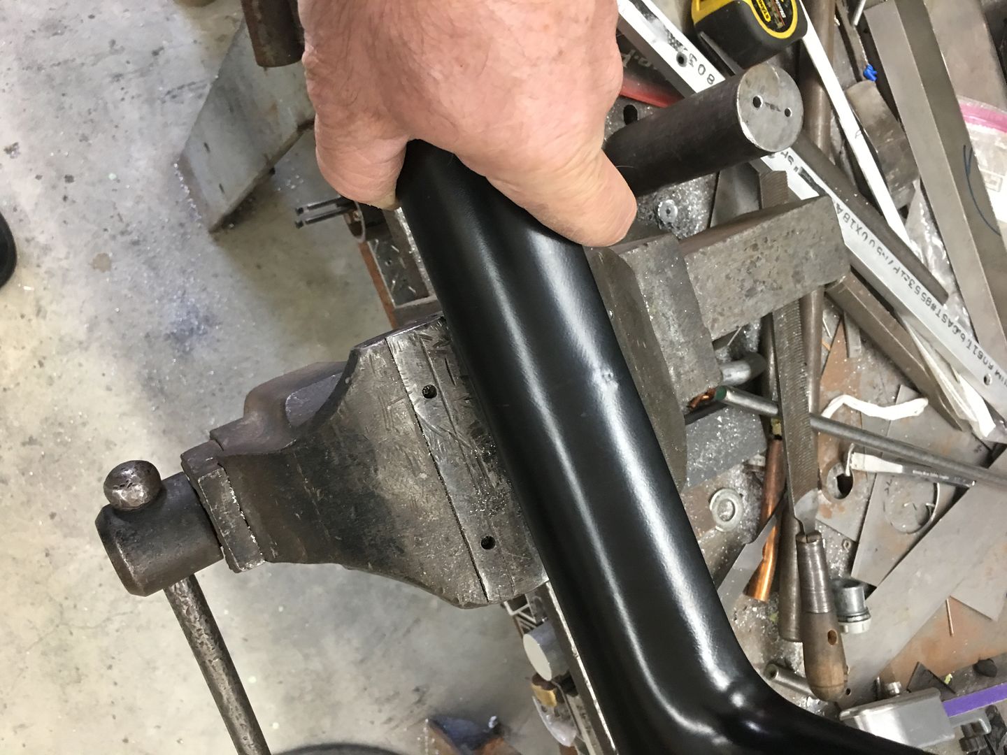
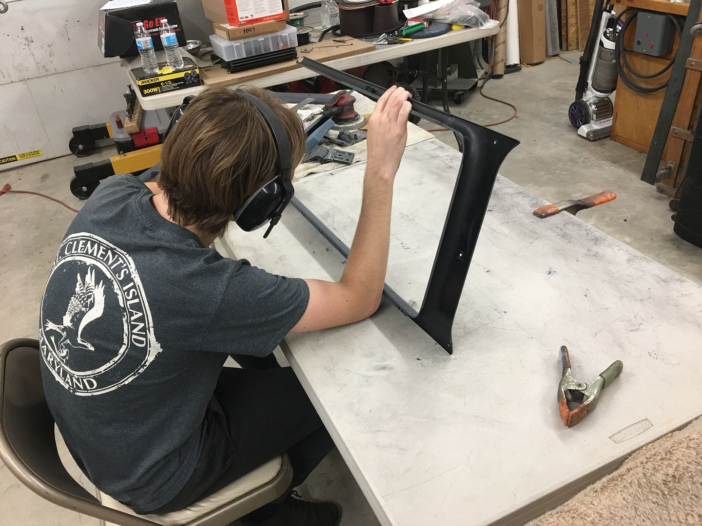
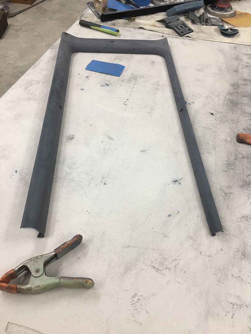
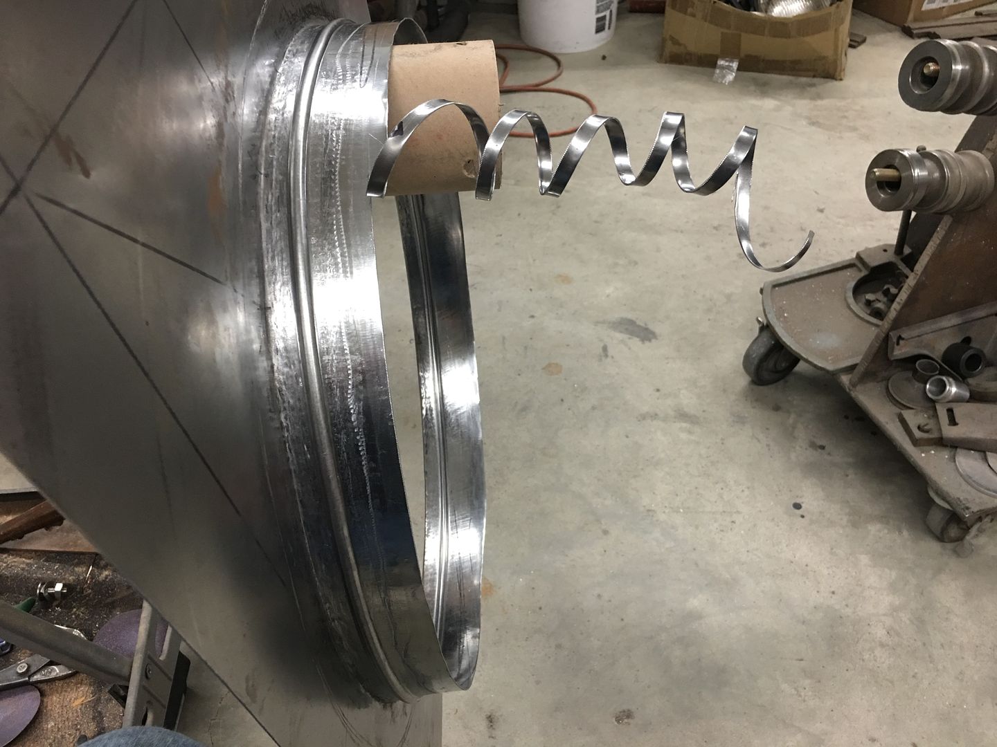
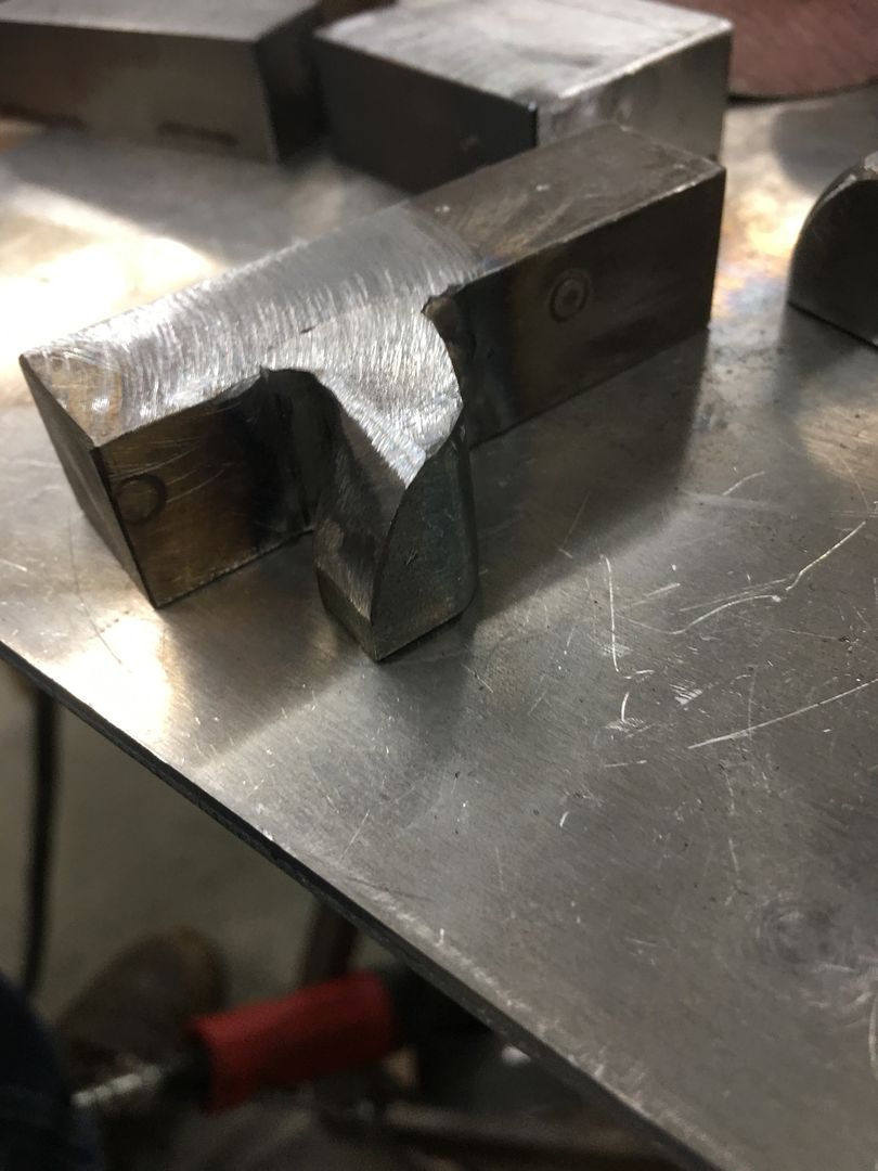
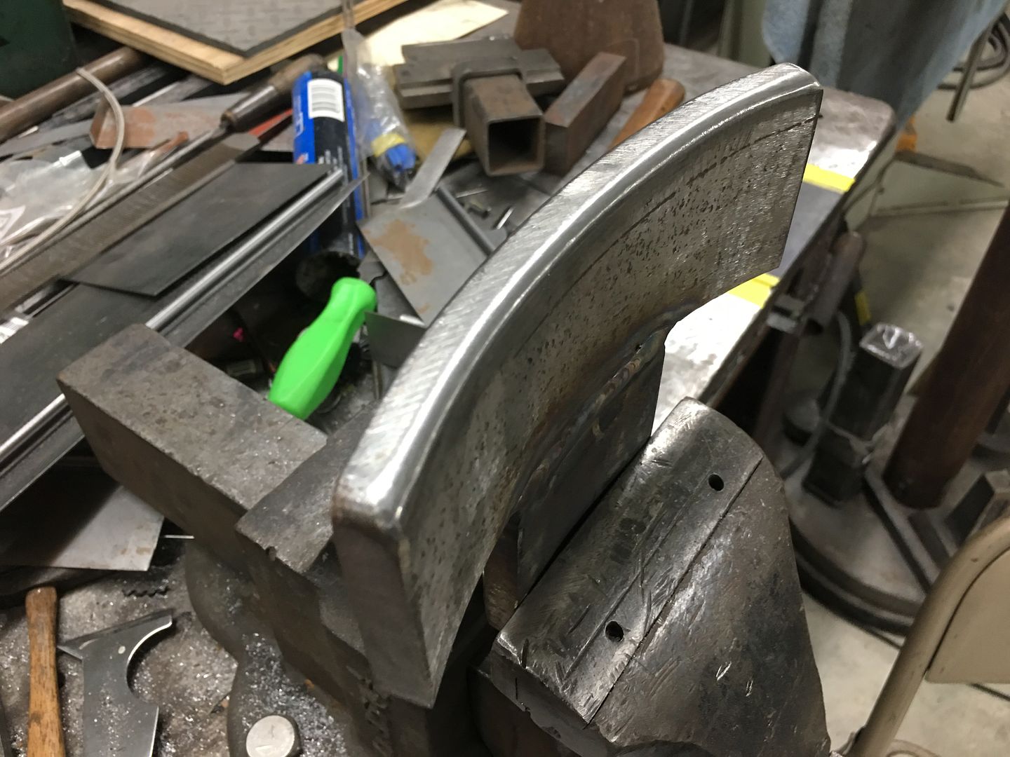
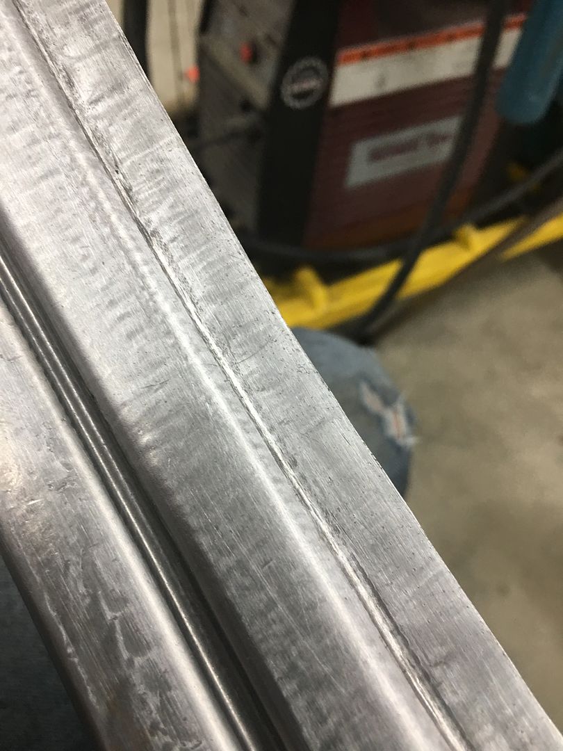
Jared has been working on blocking some of the window garnish moldings, and found some low spots. The long sections on many of these when made at the factory were fabricated in multiple pieces and butt welded together in much the same fashion as band saw blades. The front, exposed side would be sanded smooth and the rear side shows a line of weld slag. (see red outlined circle)
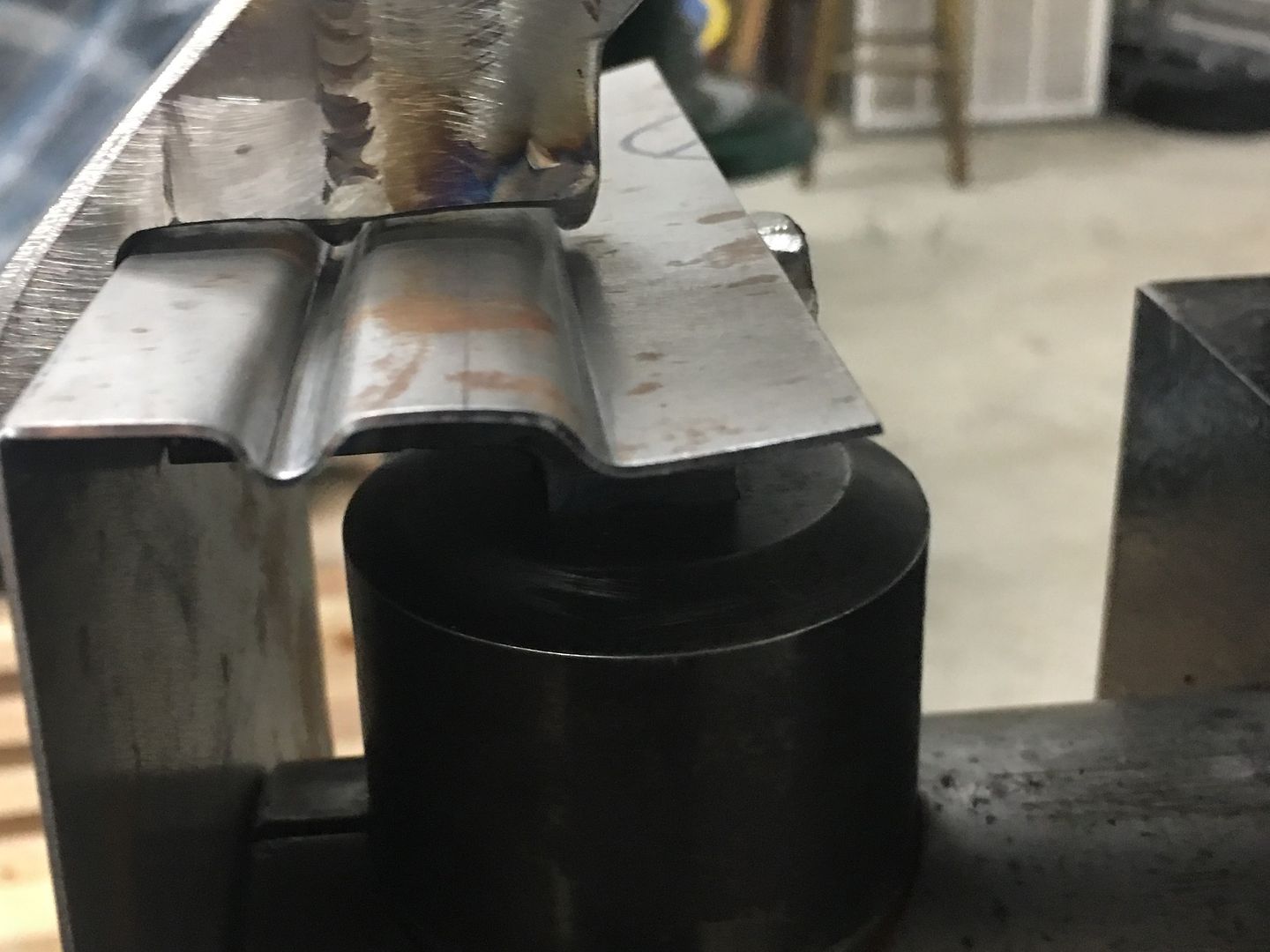
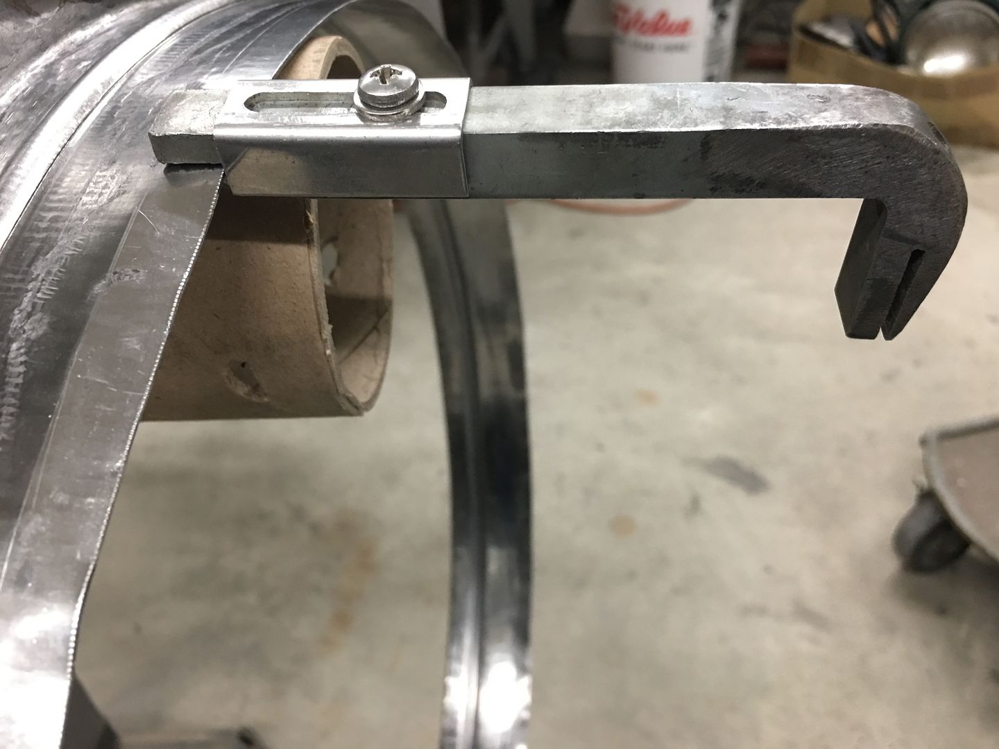
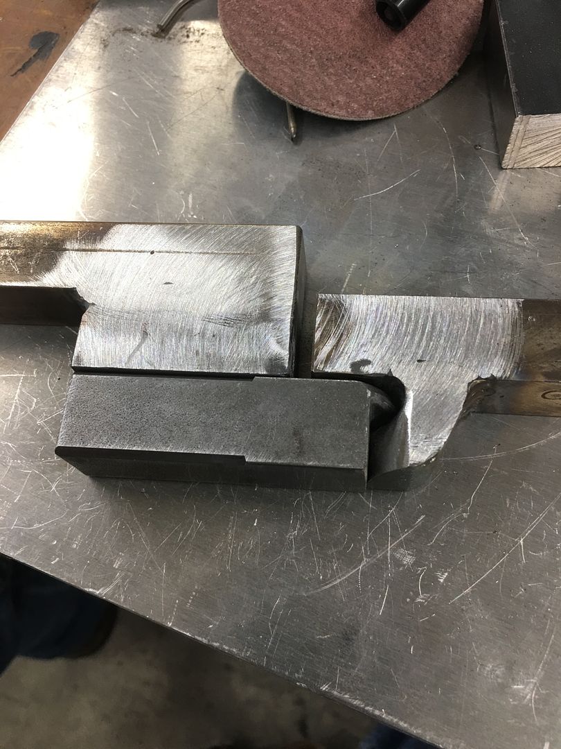
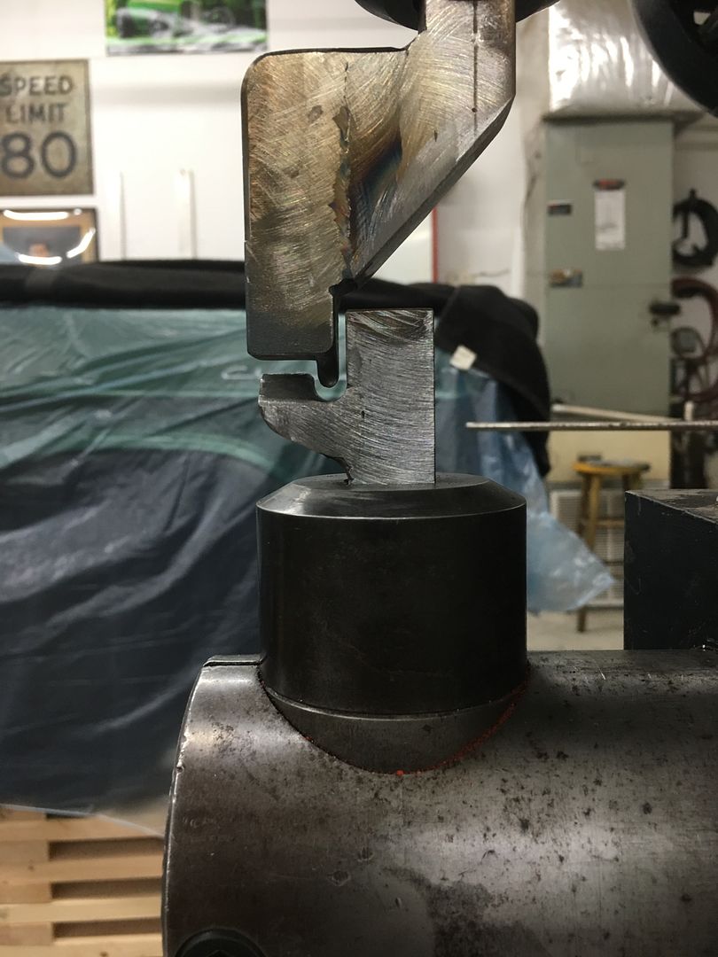
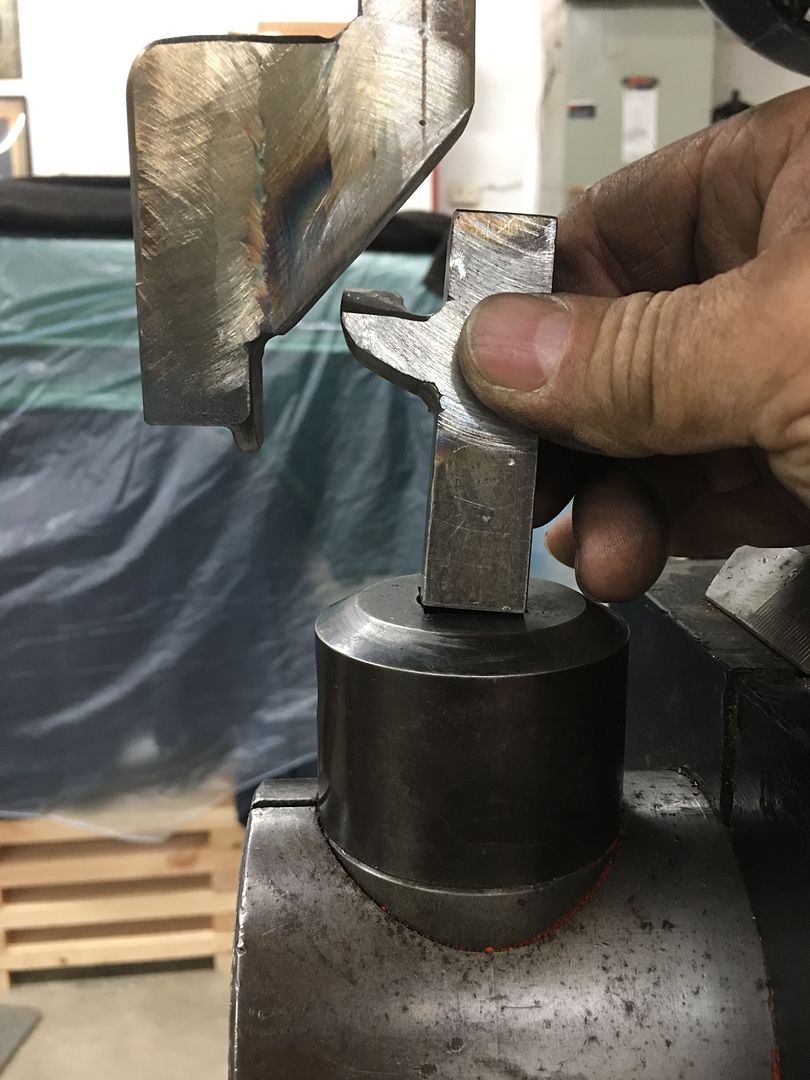
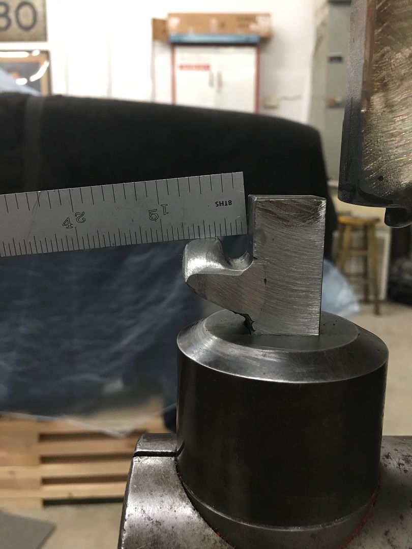
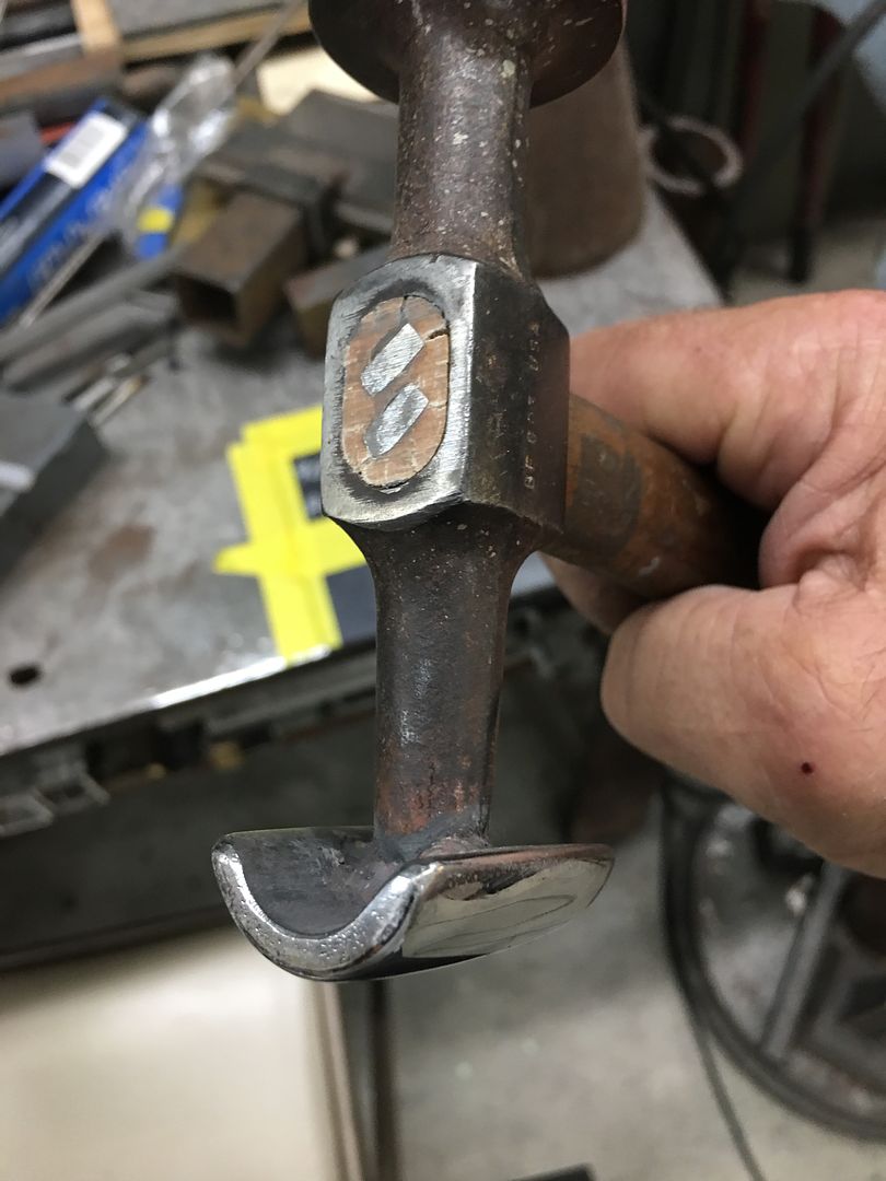
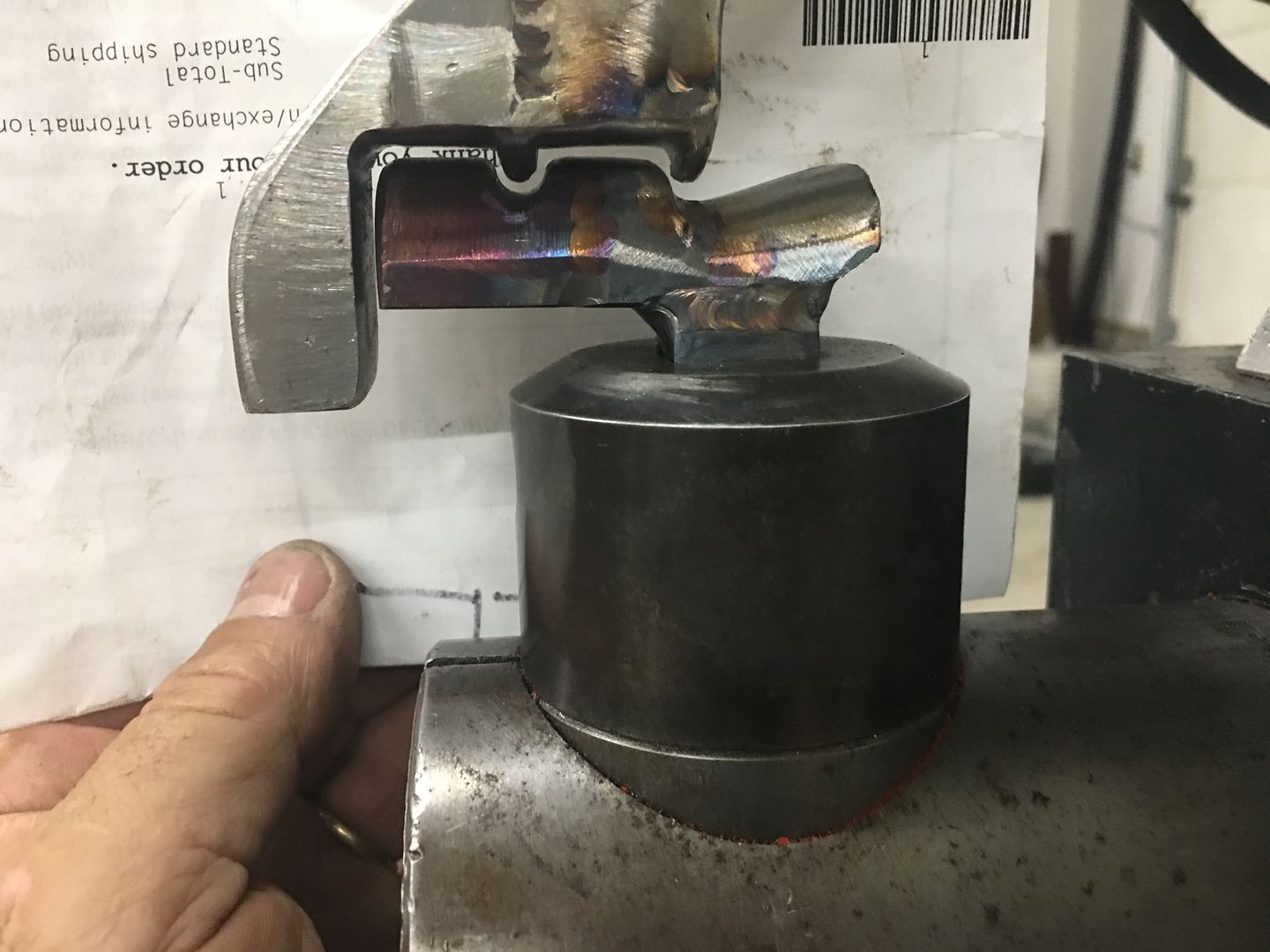
So we had a couple that showed low areas, but could not readily metal bump with the slag on the back side.. So another tool was made with a notch to accommodate the weld line....
This allowed us to bump up the low areas...
….and.....more.....blocking...….
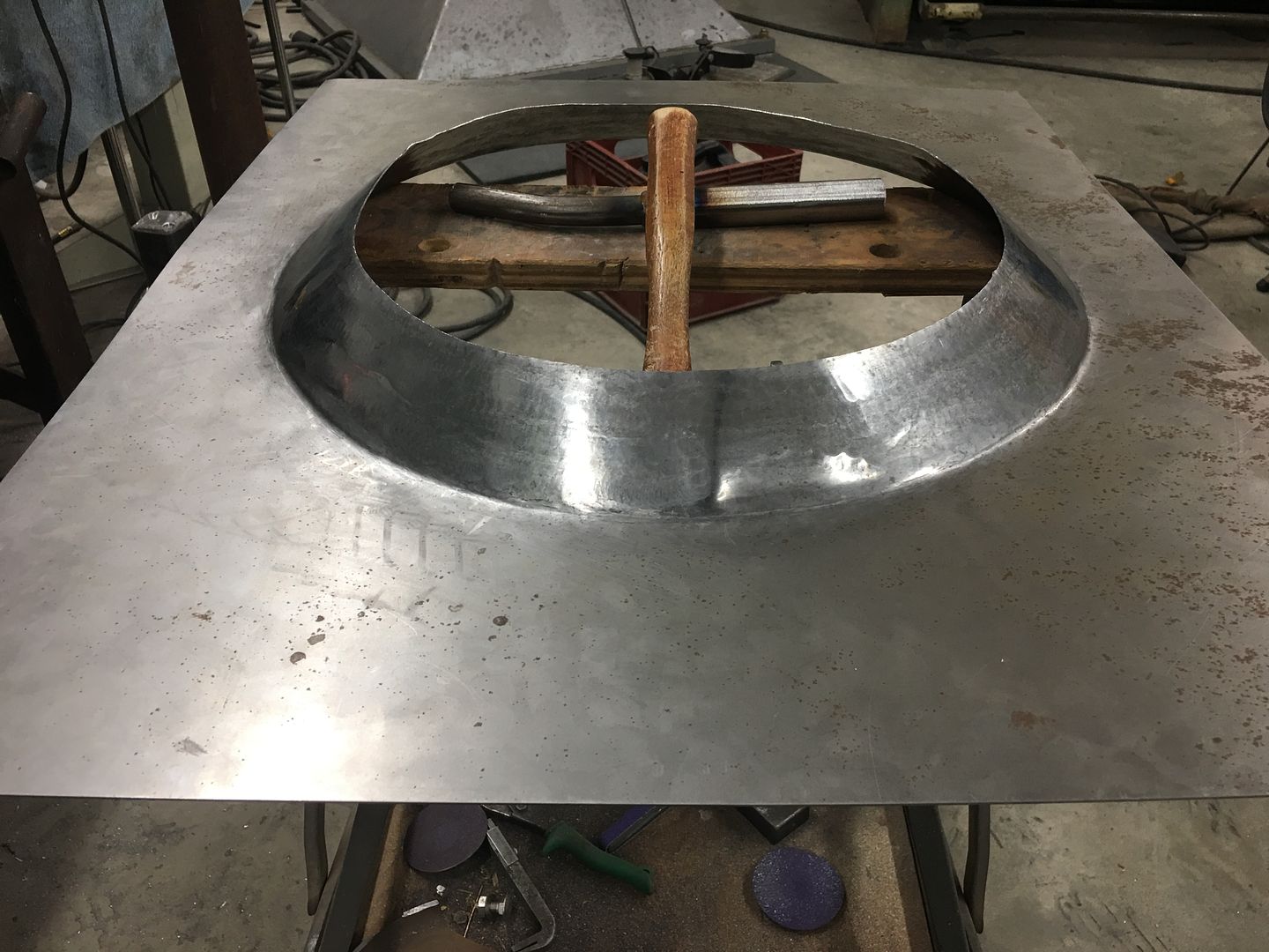
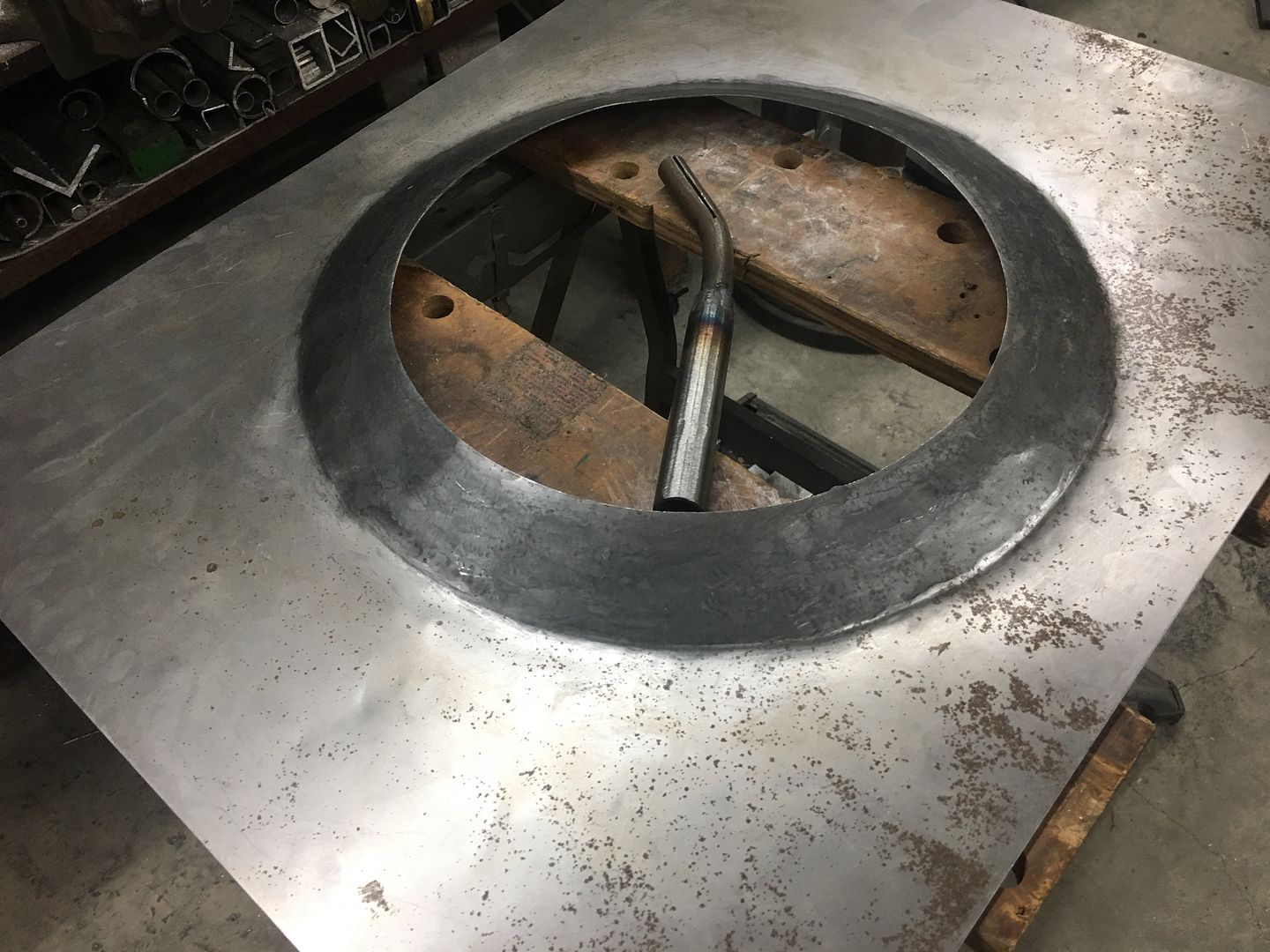
And we also got started on the fabrication of the fan shroud. Just as with patch panels, you will in most cases find it easier and quicker to make challenging parts in multiple pieces and weld the parts together. Then in other cases you want to try something to see if you can.... I give you one piece fan shroud.
https://www.youtube.com/watch?v=qJm_xZ8dEnw
Getting real close...
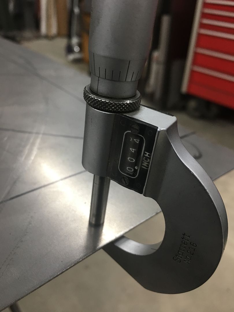
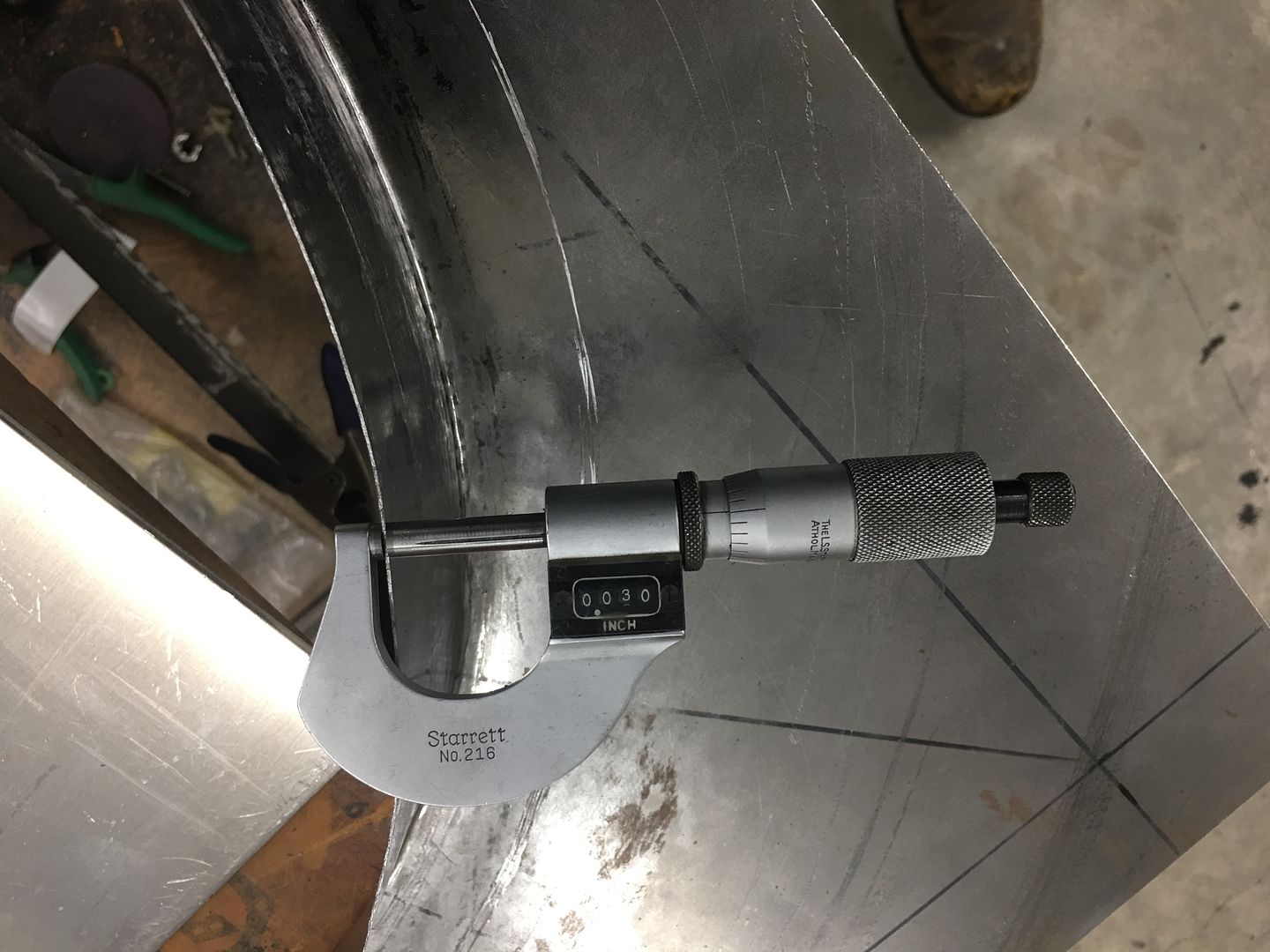
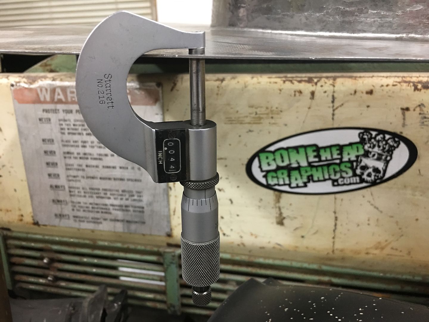
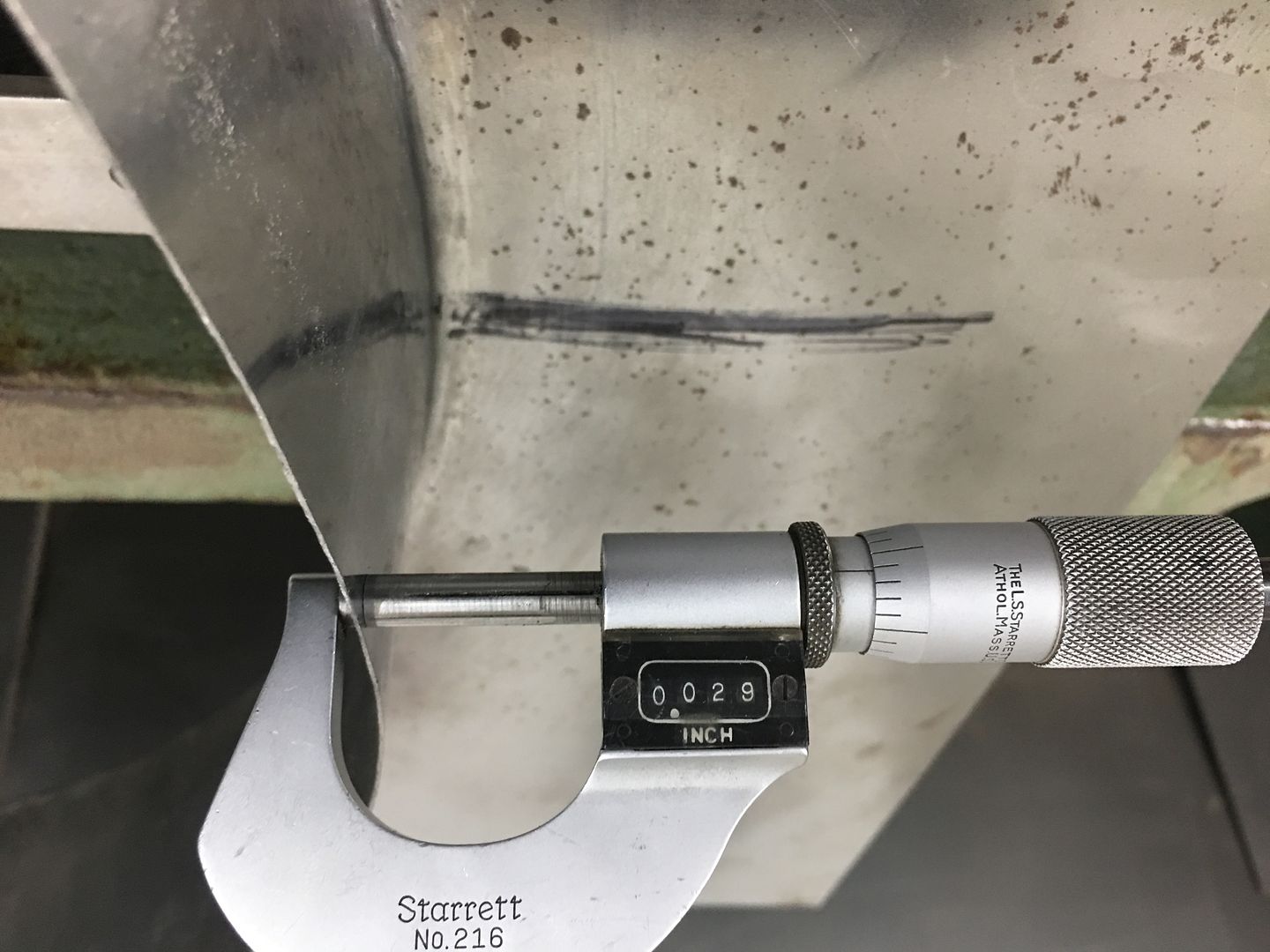
Needs a bit more work with the linear stretch dies to add some more circumference. Then we will add some bead details and a wired edge for strength. To show how much stretching we've done, the metal has gone from .044 thick to .030 at the flange edge...
And Mike was busy with buttoning up loose ends that we can do a test fire, hopefully this coming weekend, if we can get a parts delivery before then.
Robert
-
07-07-2021 01:05 PM #1628
The next couple of posts will seem more of a lessons learned than progress of any sort.. Back in my youth many decades ago I was witness to what occurs when one of your siblings was too big for her britches and back talked my father. A quick back hand and she didn't do that again. From that day on, I have been a firm believer in learning from other's mistakes, so hold on and enjoy the ride. It isn't too painful..
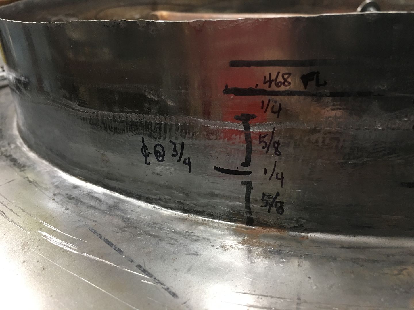
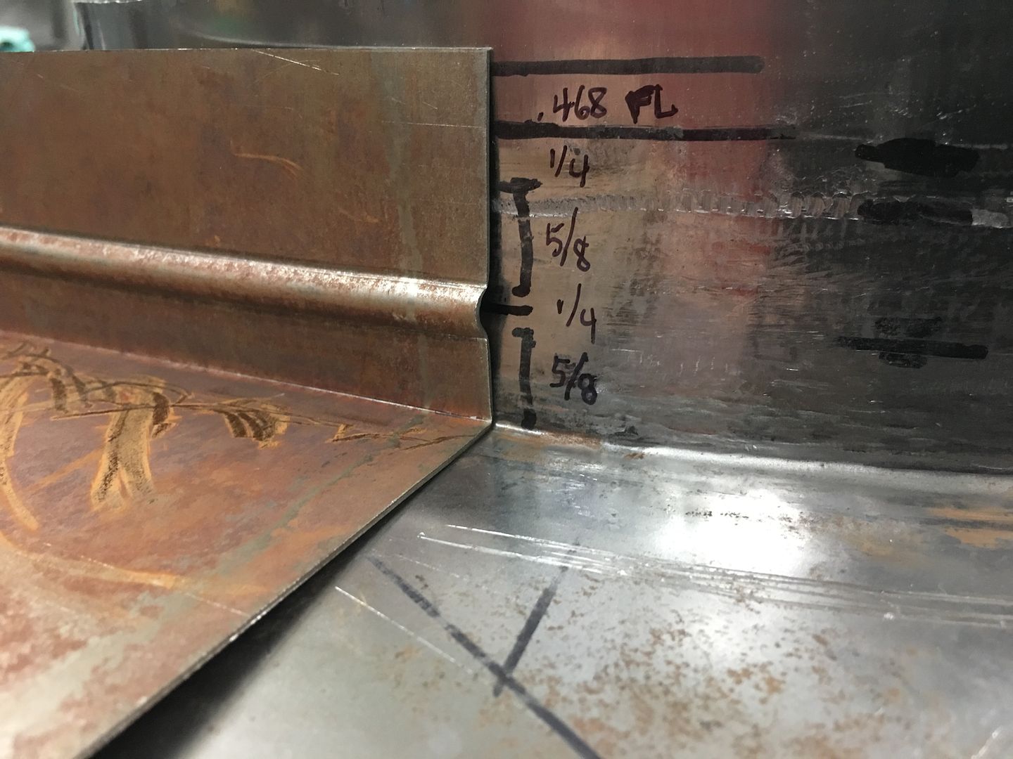
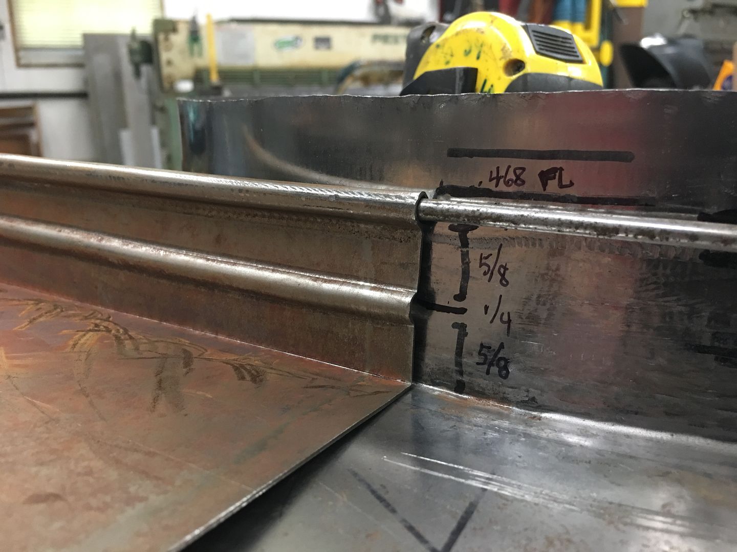
With the fan shroud formed it was time for a bead from the bead roller, and we planned on a wired edge to add strength, concentricity, and improve the looks. From dimensions taken from the rear flange of the core support (our fan shroud mounting location) to the center of the fan worked out to about 1-3/4". So given that height, these are the dimensions we came up with for our beadwork.. Typical wrap for the wire edge is 2.5X the diameter of the wire, so given 3/16 wire our flange for wrapping should be .468 or thereabouts..
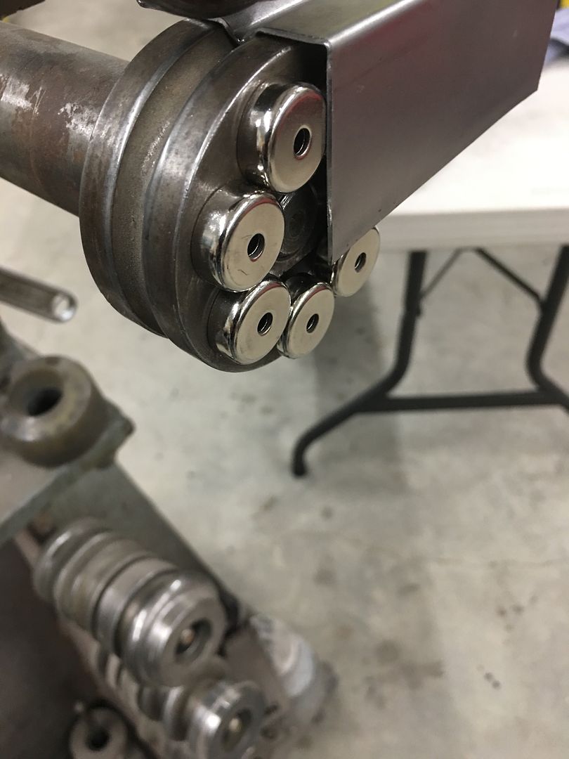
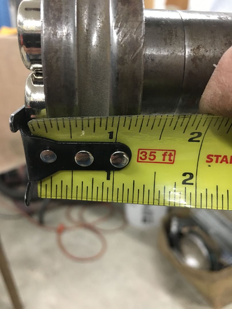
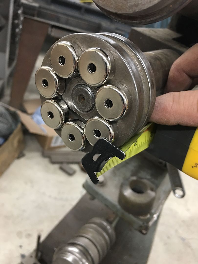
The bead roller die that matches our wire edge size was not correctly dimensioned to be able to use as a backstop, so some "filler" in the form of rare earth magnets gave us the dimension we were looking for..
So using the bead roller and the joggle dies from the Biederman hood sides, the bead/wire edge was added to our test sample.
That looked about spot on, so the bead roller was used to add the center bead on the fan shroud, and the edge was cut to size and tipped to a 90* angle..
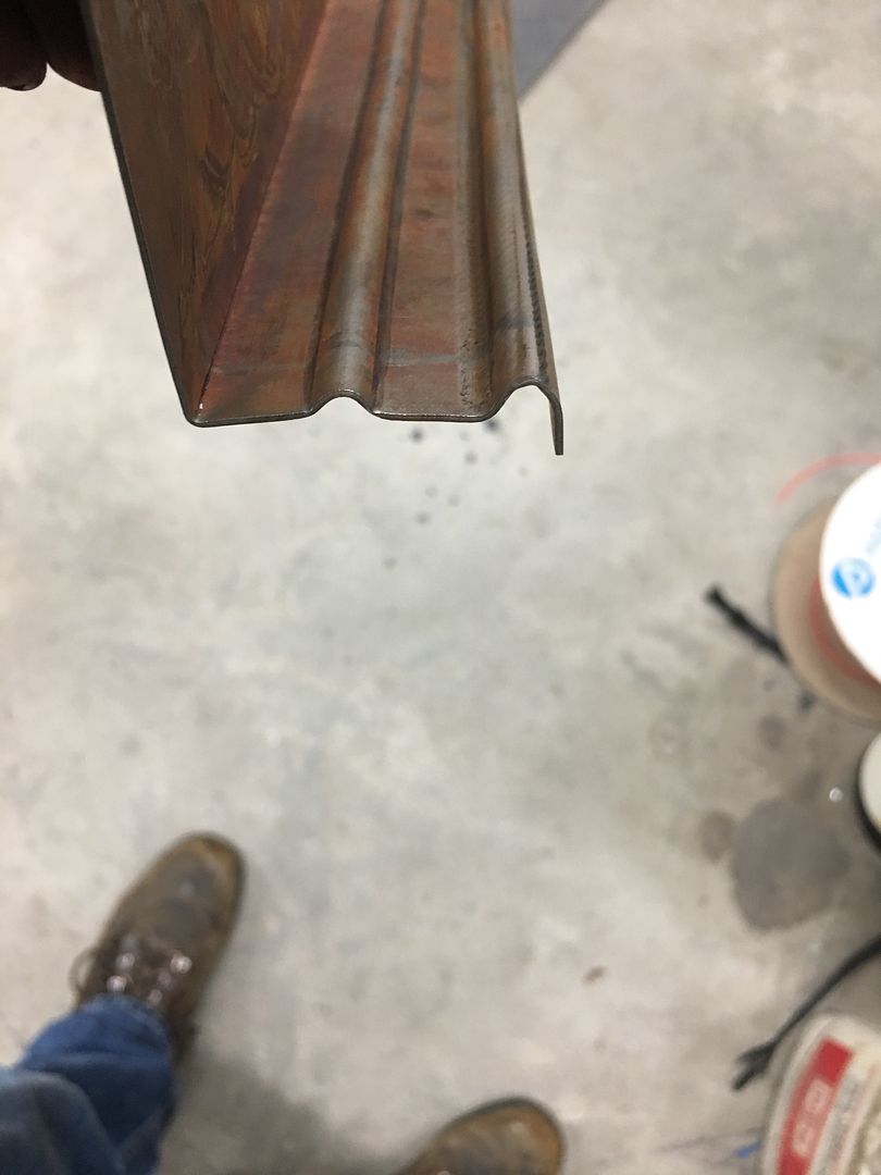
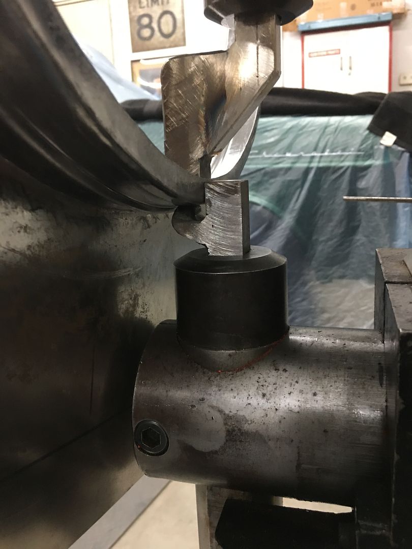
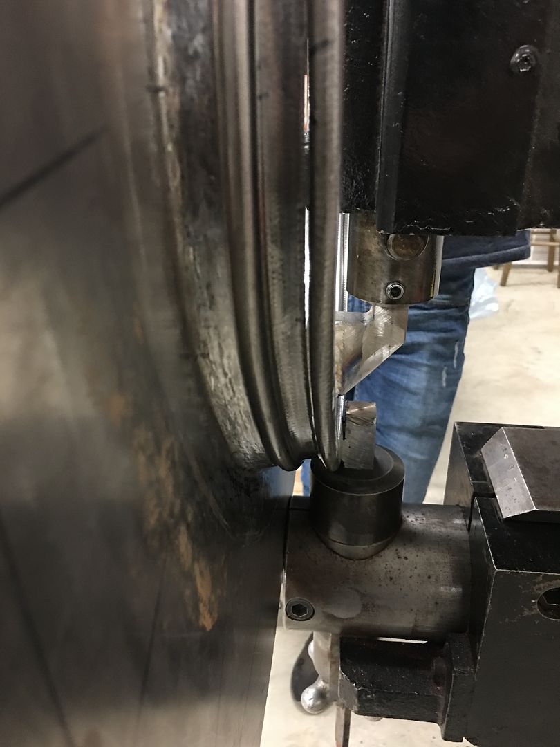
Now to use our joggle dies to add the outer bead detail.... which looks like the shroud mounting flange is in the way.. Did I say one piece fabrication was harder?
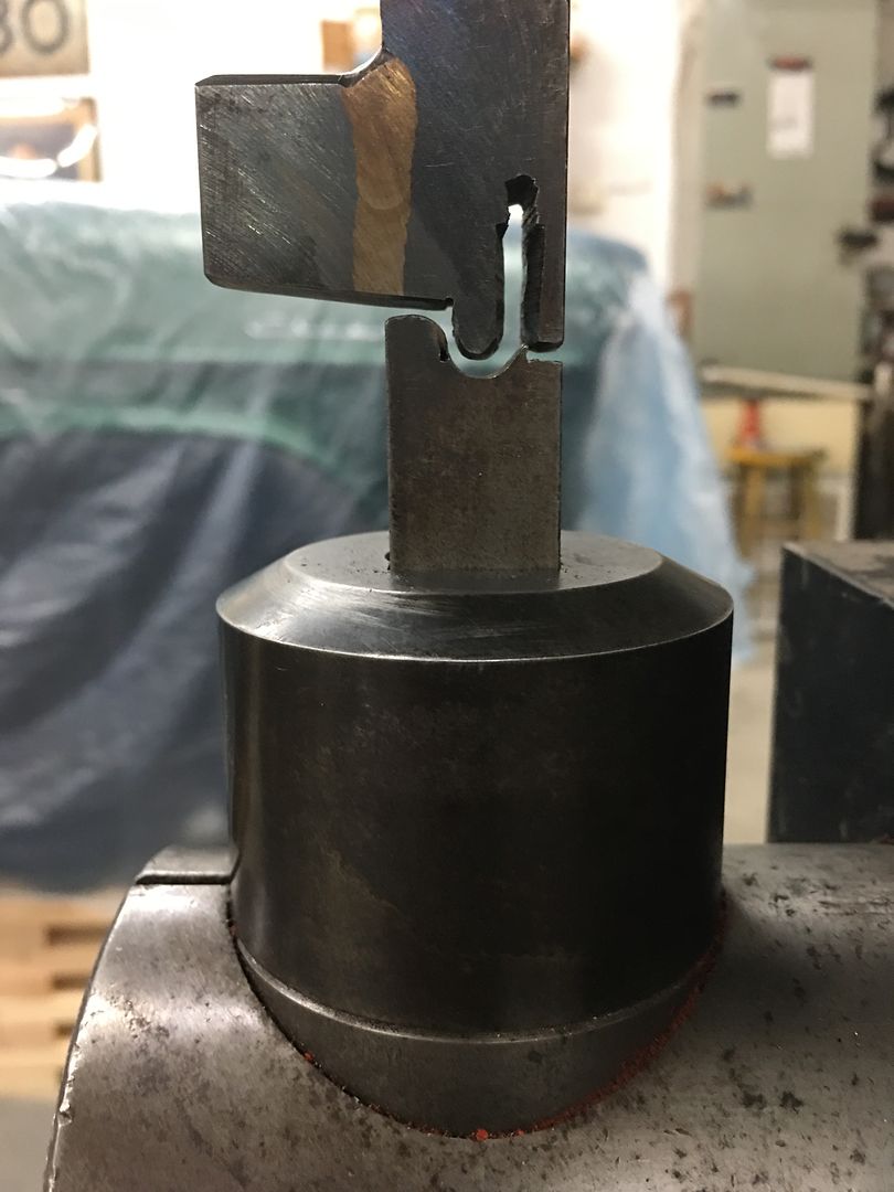
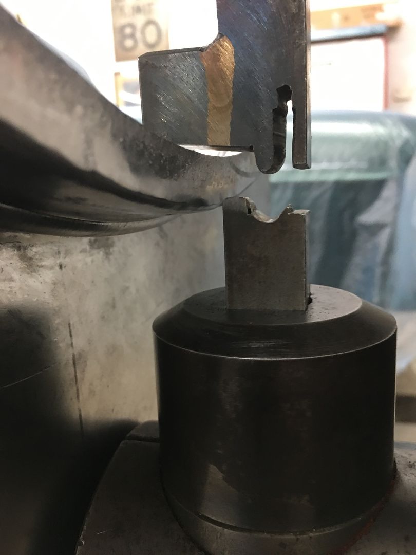
So a new die is in order, for the bottom we have a sliding lower toolholder so that will accommodate most of the offset there. for the top, we need to stack some dies to get the offset needed.
The upper die also needed a 45* relief on the bottom for installing the lower die.
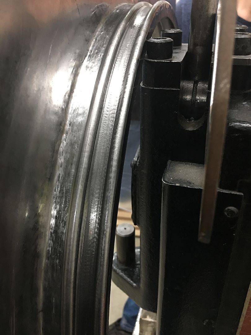
Looks much better...
Our speed run...
https://www.youtube.com/watch?v=nyylI6tybew
.....and this happens on the last pass..
Robert
-
07-07-2021 01:18 PM #1629
That sucks. Man that is so much more detail than I could imagine doing to a fan shroud.
-
07-07-2021 02:31 PM #1630
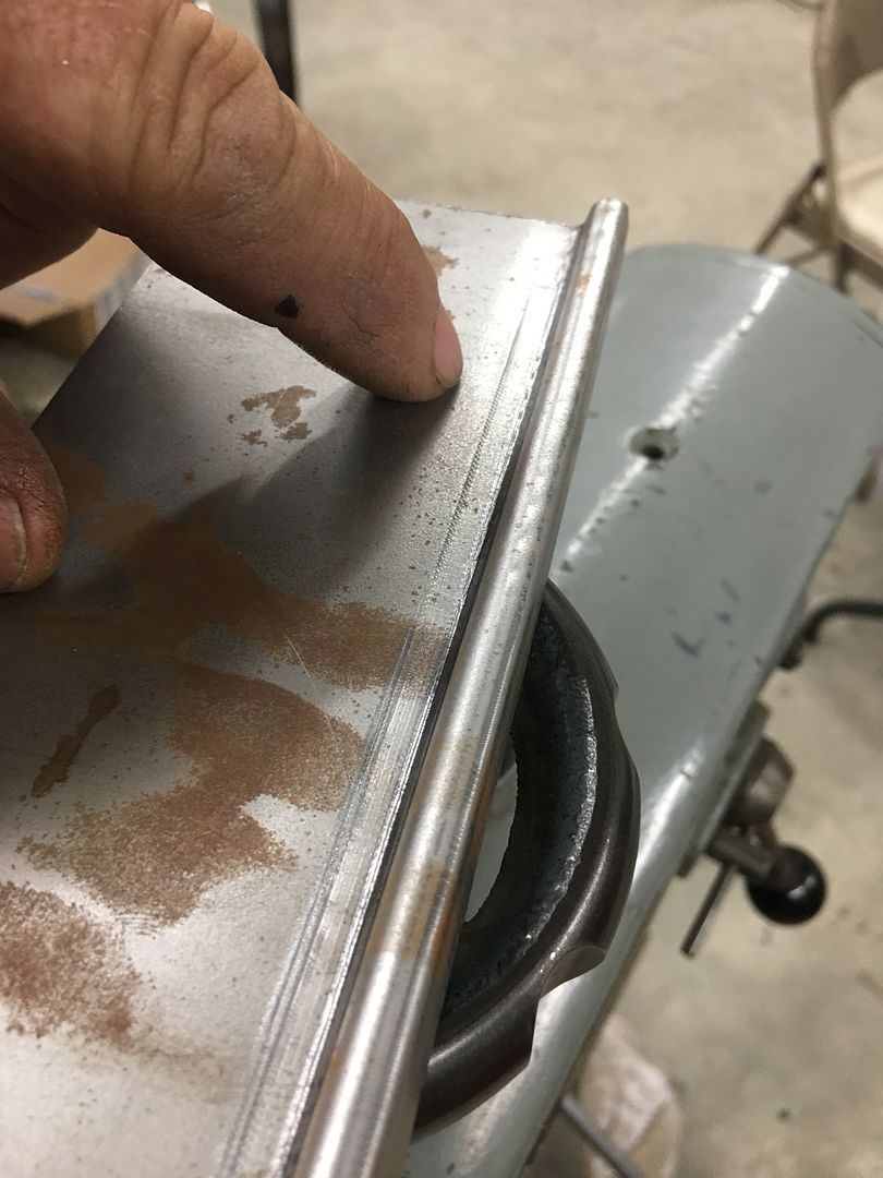
So now for some hindsight. When we had done a flat test sample we noticed the edge of the lower die had made a crease (finger point). To alleviate this, I will normally taper the dies so the edges aren't tight together, in hopes of curing exactly that.
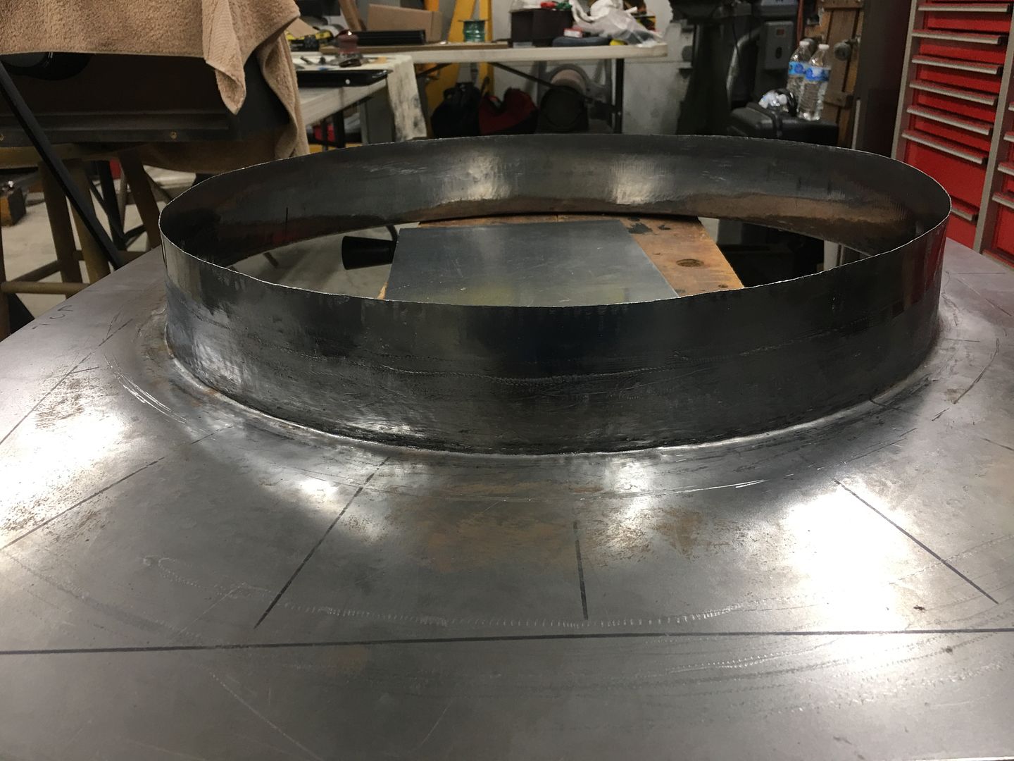
Looking back, this slight defect would have been at the edge of the center bead and likely not noticeable at all. Next, between this taper and the ~1/2" flange not wanting to stretch, the resulting shape matches the bottom die, and pulls the shroud circumference inward.. which was not desired either. So moving forward, rather than a folded flange here we should opt for an offset first for more flexibility in stretching outward for the bead detail, and then fold the flange last.
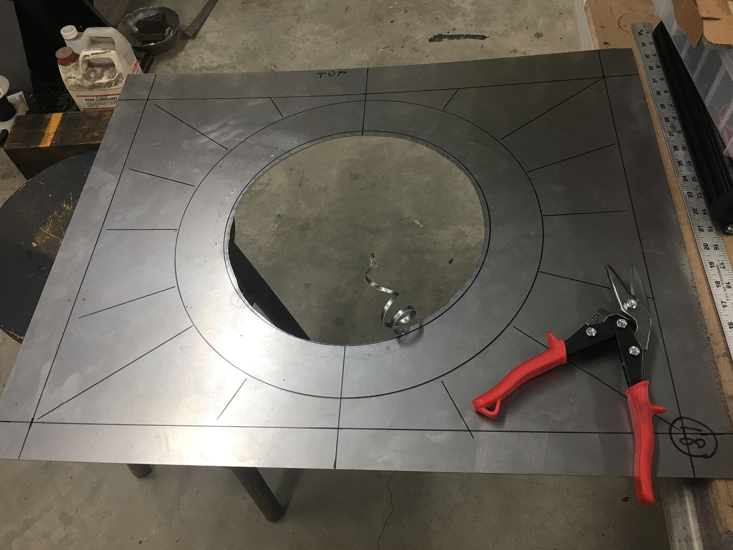
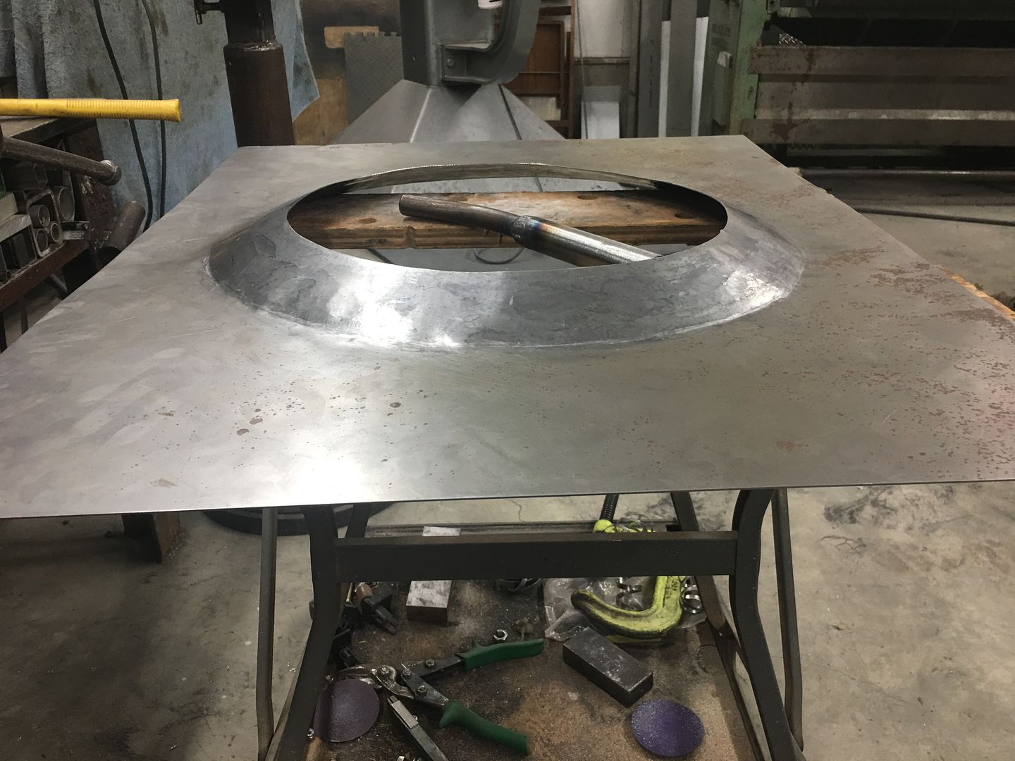
So given our misshapen and slit open fan shroud is no longer viable, what's a person to do? I'm not one to so easily throw in the towel. More accurately, I've been called hard headed. So here we go with the second take of Fan Shroud fabrication. And since we missed this step last time, take a look at this video having just cut out the center hole..
https://www.youtube.com/watch?v=hakmD7Wn4f8
There were absolutely ZERO burrs as can be seen. If your tin snip game is not at this level, please watch this instructional video by my friend and fellow metalshaper Bill Gibson. He will explain exactly what you need to do for the same results...
https://www.youtube.com/watch?v=qAOQfUaRZyw
I had been using tin snips for DECADES and watched this video, quickly learning what I had been doing wrong for so long...
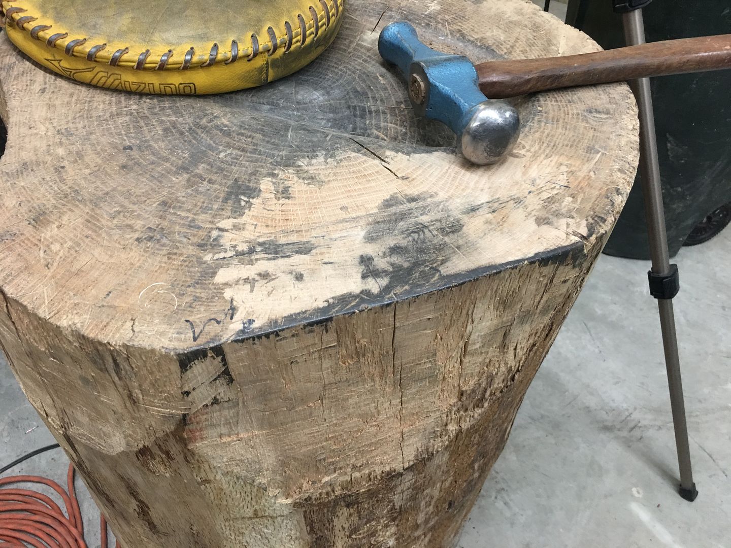
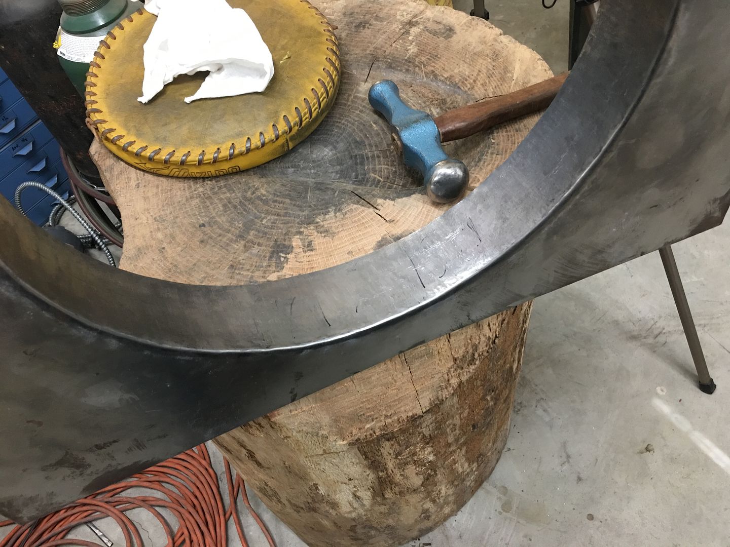
....and then back on the NEW fan shroud, stretch with a blocking hammer on the stump, tip the edge, stretch again, until we are able to get the shroud into the power hammer...
and using the power hammer....
https://www.youtube.com/watch?v=NqGRLIFKQ1o
https://www.youtube.com/watch?v=FyCR6sI8TUU
Getting close, we're down to about 10% more to go...
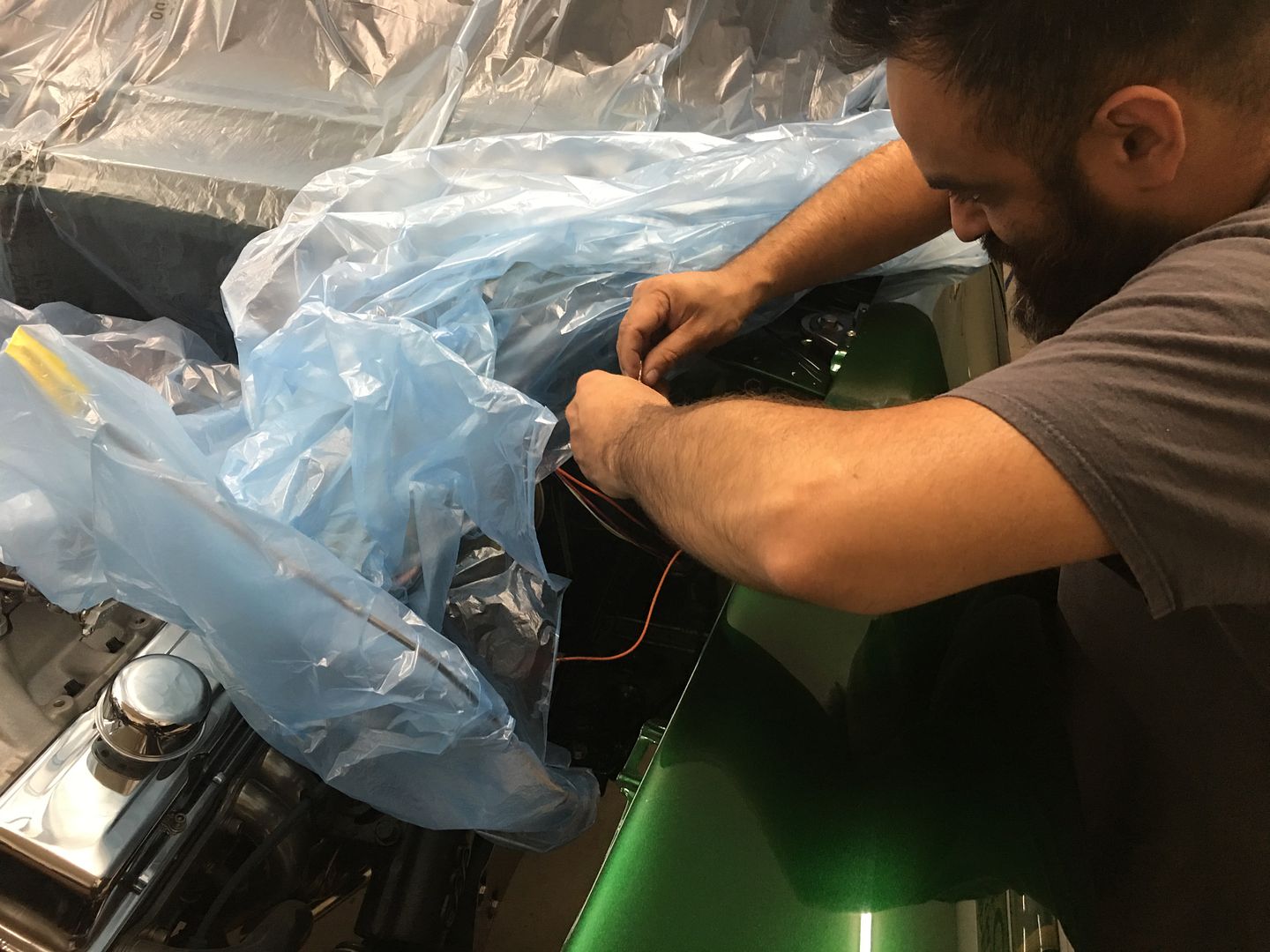
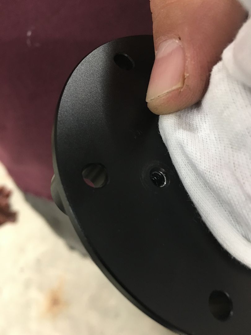
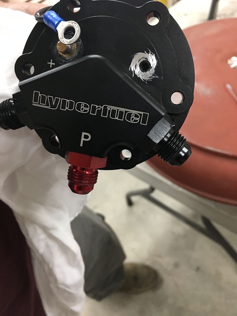
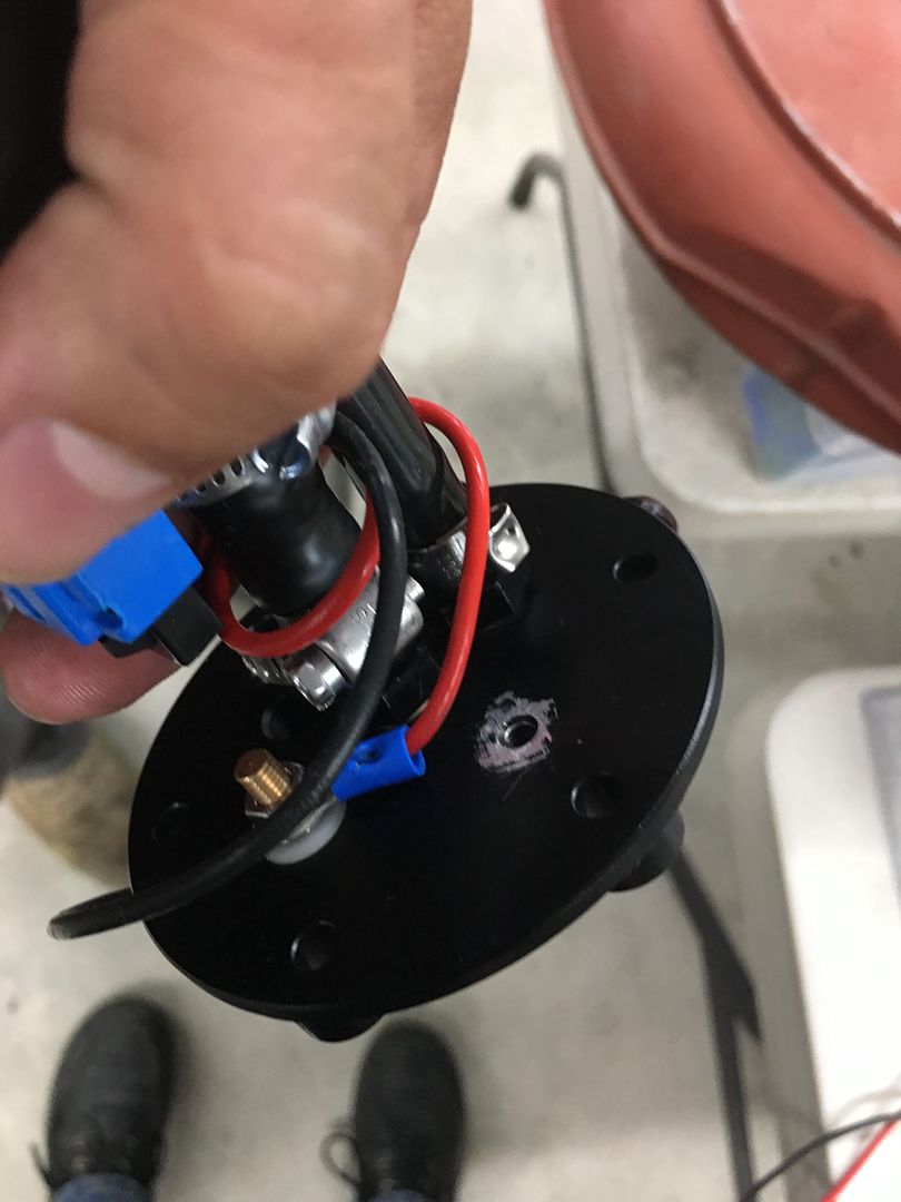
In between all that fiasco, Mike was working on getting the car test fired. All the temporary wiring connected, and for some reason we had no fuel pump action. OK, third time we've dropped the tank in a week, and removing the pump we find NO connectivity from the outside ground to the inside ground. WTF?
Lo and behold, there is no pass through on the grounds but each (inside and outside) has their own bottom tapped hole. It would appear the tapping occurred PRIOR to the anodize finish, and you know how well that conducts.. The burnishing brushes wouldn't touch the stuff, so we used some sharp implements of destruction to allow a ground path...
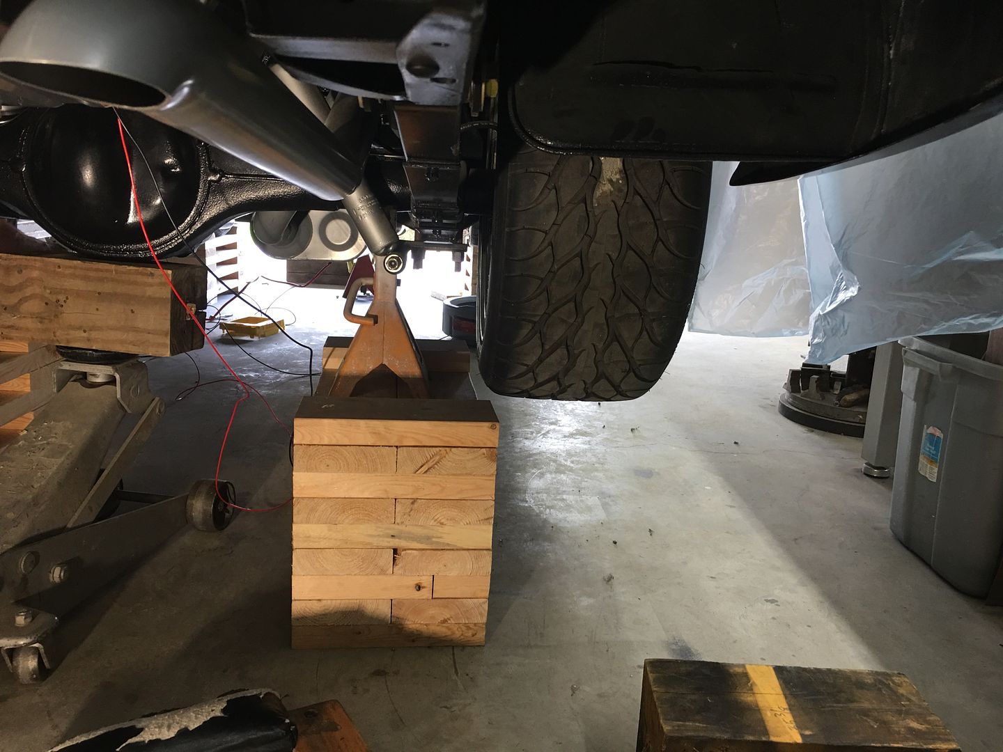
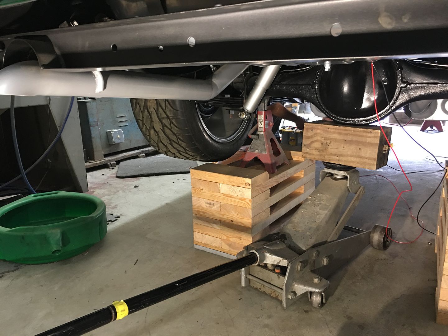
That fixed the issue, one that should not have been there from the start. Next, in the interest of safety, lets move the rear "lift kit" from the tires to just inboard using jack stands..
So now with a bit of fuel pressure to work with, we give you a rumble... We still need to adjust the air/fuel ratio but it was good to hear this after everything else the past couple weeks..
https://www.youtube.com/watch?v=MoIjmmmXtO0Robert
-
07-08-2021 09:22 AM #1631
Congratulations! A start up is always a sign of nearing completion. Job well done!
The shroud is awesome, I surely get the start over and see if it can be accomplished.
You never disappoint.
Thank you Robert for all of your sharing.
ScottScott
31 Ford five window
-
07-10-2021 03:06 PM #1632
Incredible job; that’s some serious craftsmanship.1 Corinthians 1:27
-
07-11-2021 11:28 PM #1633
More progress on the (second) fan shroud, but I had a request to show the process in greater detail.. So we'll start with the beginning.
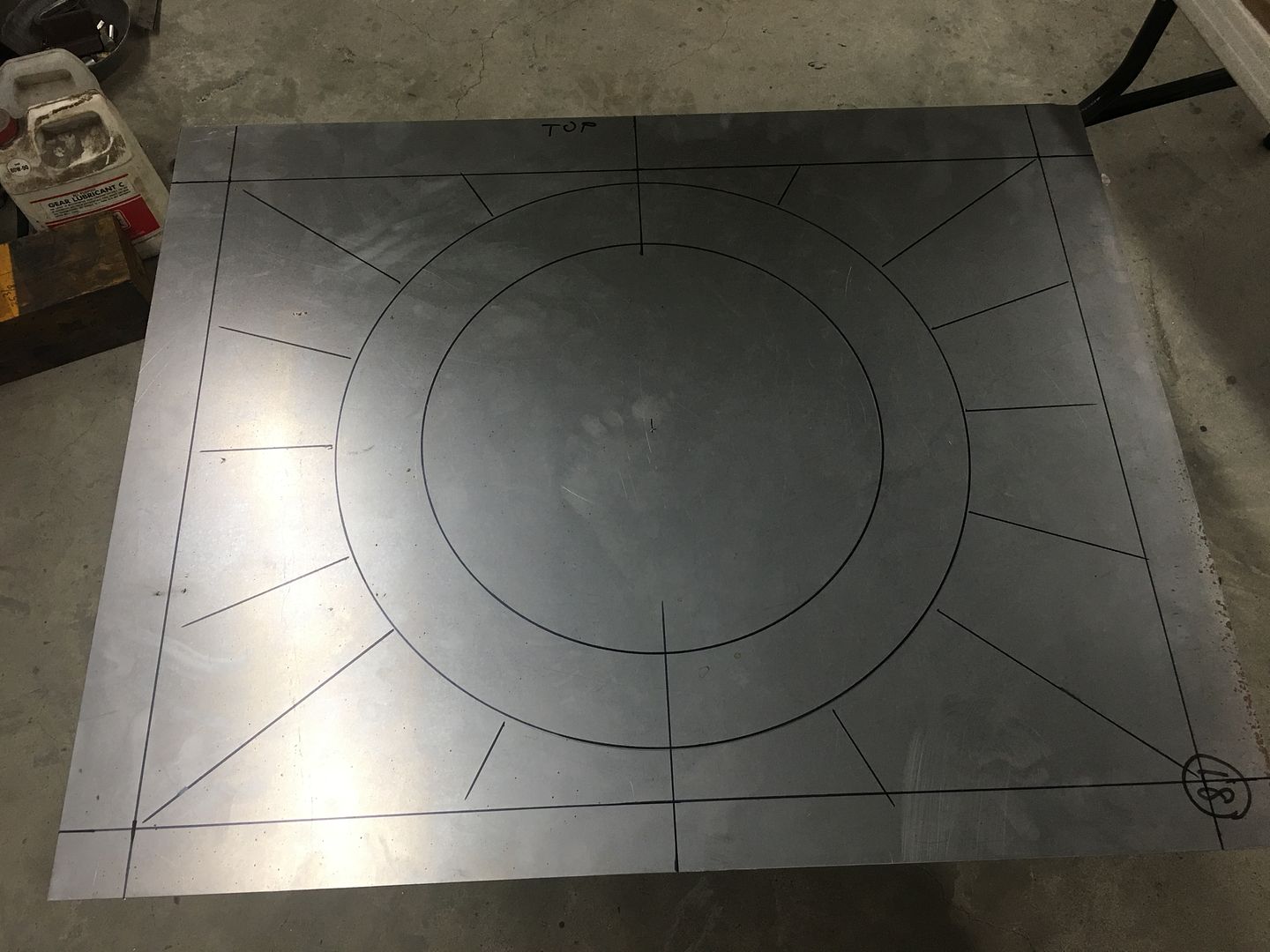
First was the layout of the bend line, and then the cut line was located about 3" inside of that. (I'm using some of the pictures from our first attempt as our shop photographer missed some the second time around)
The initial stretch was done using a blocking hammer on the top (flat area) of the stump, primarily at the inside edge as that needed the most stretch.
On our first attempt we had a hammer form that was used to "set" the bend line with a crowned body hammer as we added the first bit of stretch.
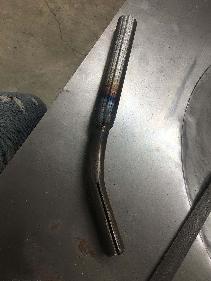
This seemed a bit cumbersome, and the second version I used a bent portion of round stock that was in the scrap pile, added a piece of pipe for a handle, and the band saw added a slice for a new tipping tool. The bend in the tipping tool gave it a built in fulcrum. Normally a tipping operation tries to pull the adjacent material along as the bend forms. In this case we set the panel on a table and used the bend (fulcrum) of the tipping tool against the table to pull the stretched area downward. This allows us to push down on the handle to elevate the panel off the table, and to push downward on the flat panel outside the bend line with the palm of your hand. This does a good job of placing the bend where needed without pulling adjacent metal along for the ride. Even though the pictures show the stretched area upward, the panel was placed with this area downward when using the tipping tool..
This worked much better at setting the bend line than the hammer form, and it was surprisingly accurate.
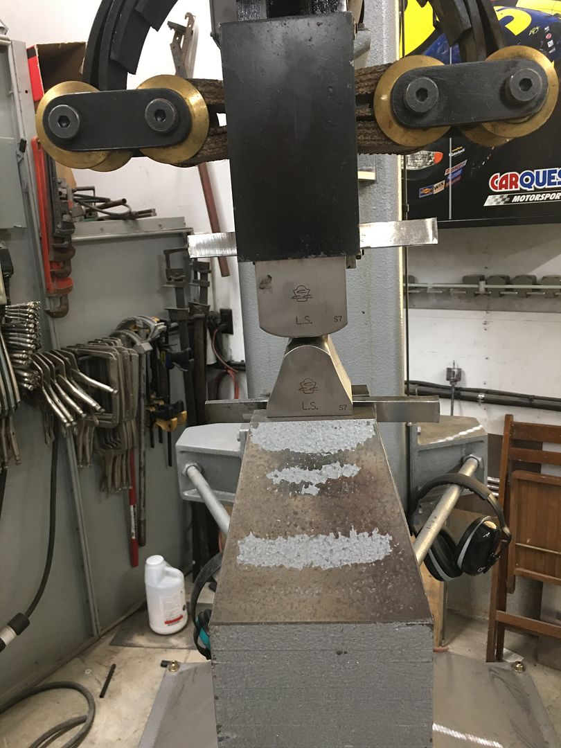
Much of the stretch was done using linear stretch dies on the power hammer, but we also reverted back to the blocking hammer and stump to better focus the stretch locations.
https://www.youtube.com/watch?v=FyCR6sI8TUU
https://www.youtube.com/watch?v=bKBy-TmkrMM
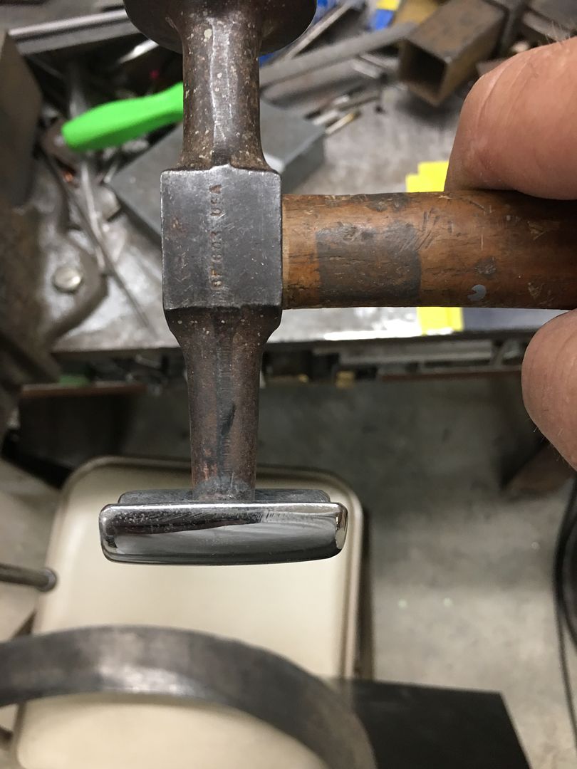
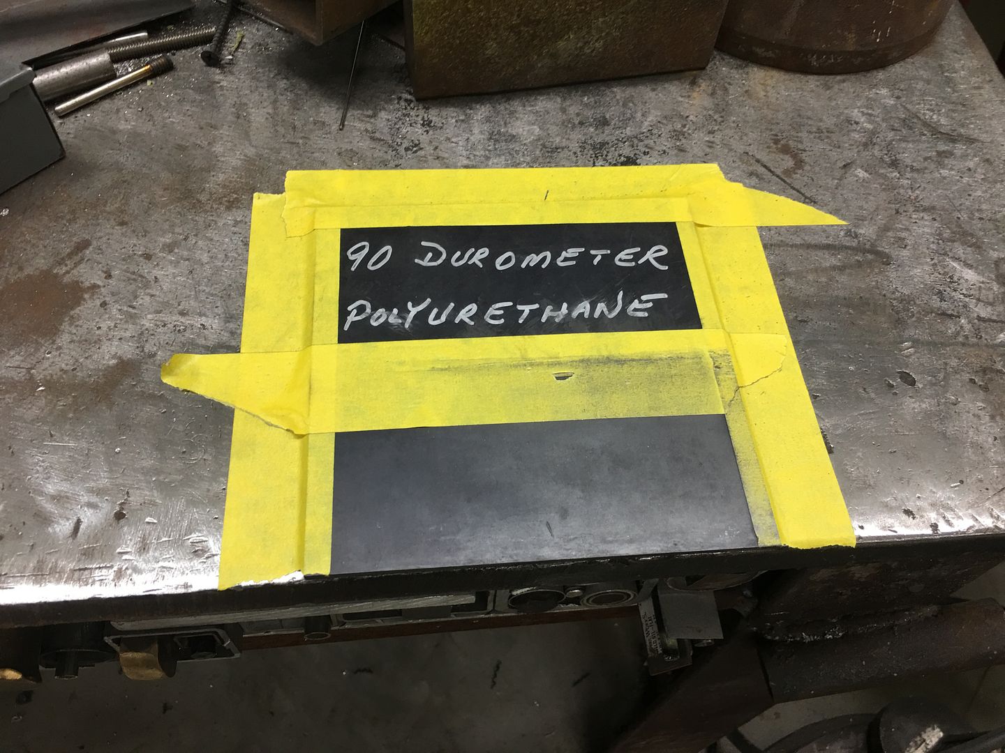
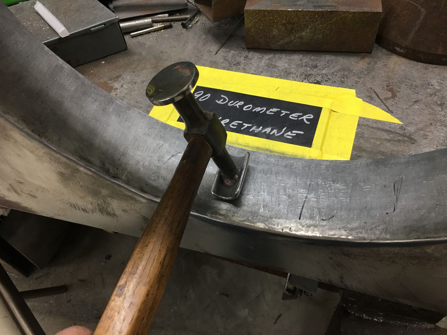
The other issue to overcome with both hammer operations was that they didn't play nice with keeping the shroud in a flat vertical. So the next tool used was a 90 durometer pad of polyurethane and the Model A leaf spring hammer. The hammer face was too short to match the shroud height (approx 3") so three passes were done to cover the entire height and with each pass the hammer hits were about 1/8" or so apart.
The bulk of the stretch was done on the power hammer, and the front of the lower die holder is missing quite a bit of paint from this job...
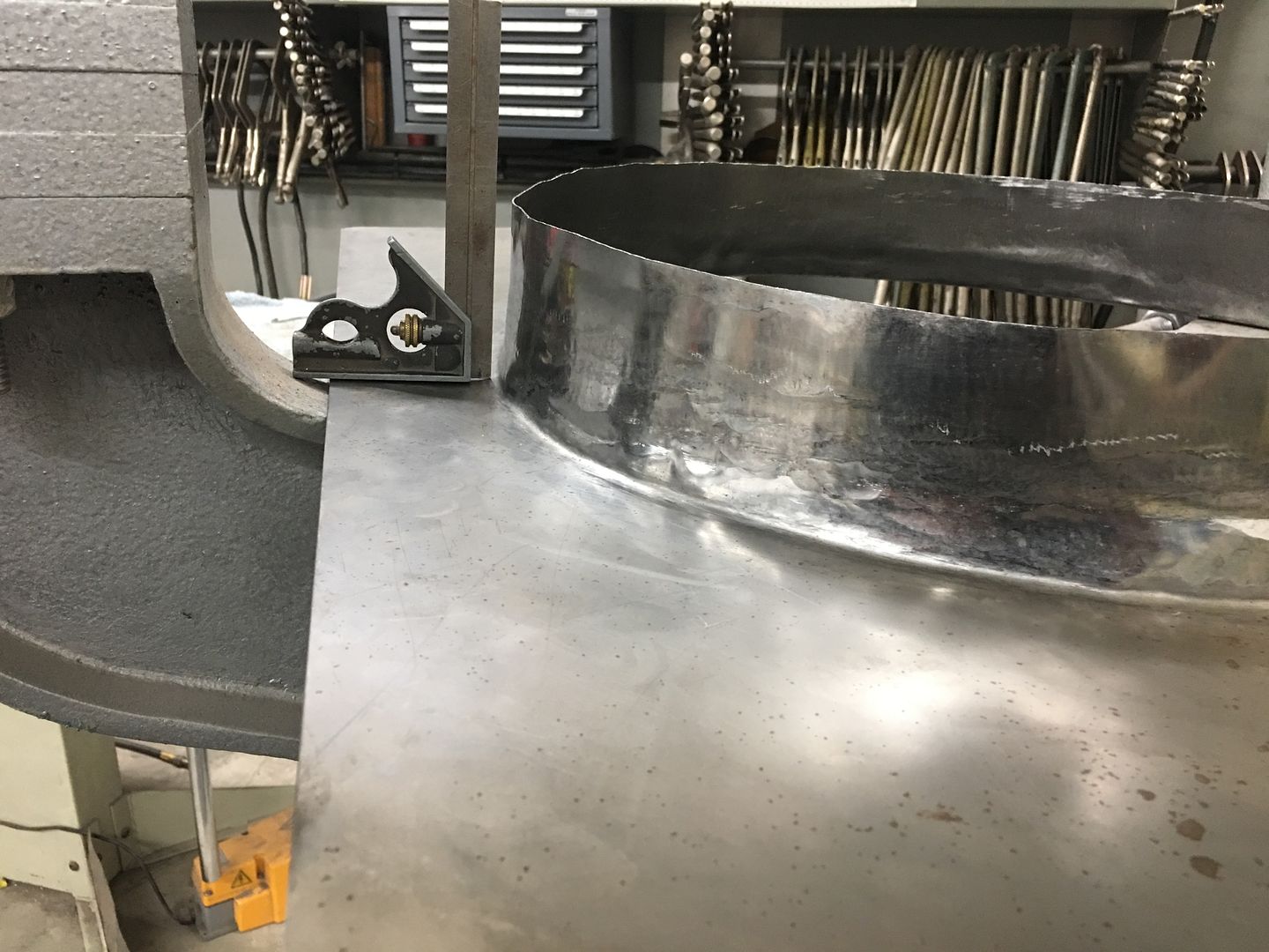
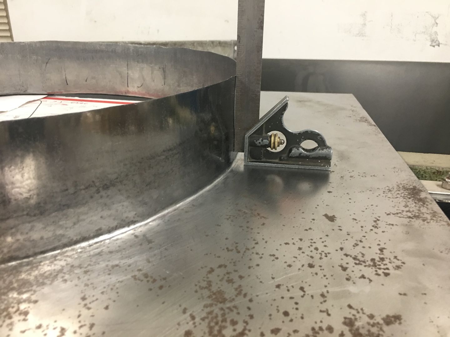
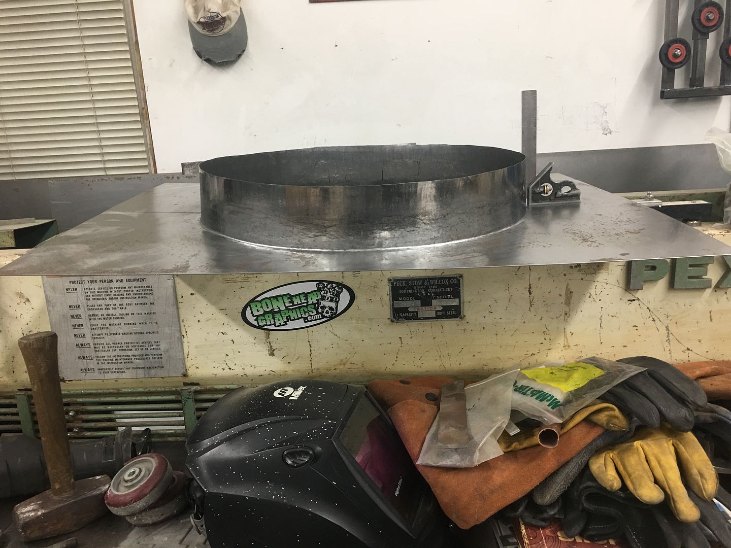
The completed bend, we started with .044 thickness (18 gauge) and it was thinned to .029 thick, or lost about 1/3 thickness to turn the 90...
https://www.youtube.com/watch?v=IdSQFxGBoZsRobert
-
07-19-2021 05:57 AM #1634
More progress... using our rare earth magnets on the end of the bead roller die to correct the "back spacing", the fan shroud has the center bead added...
https://www.youtube.com/watch?v=cRXF3sInnTU
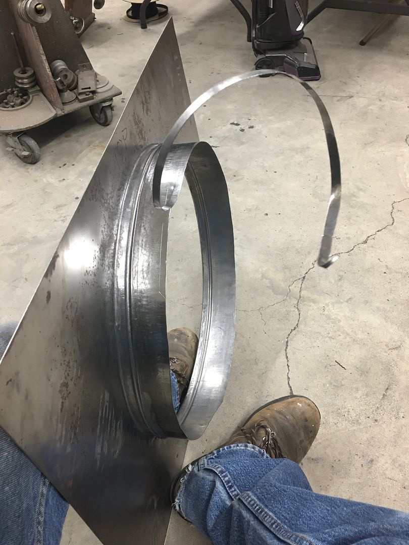
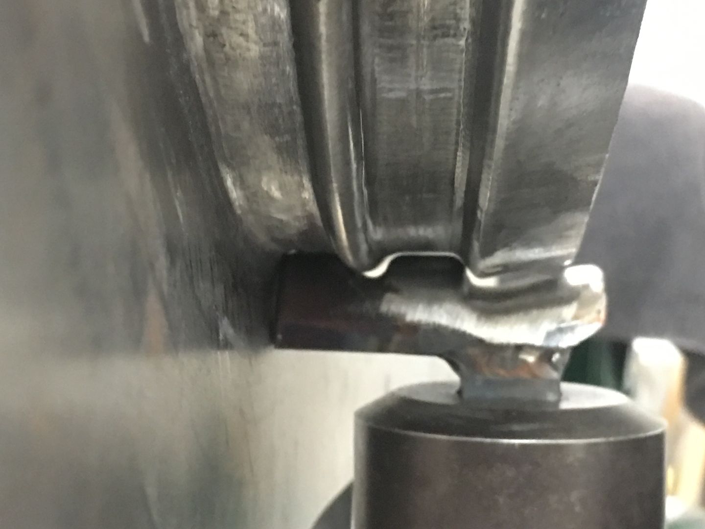
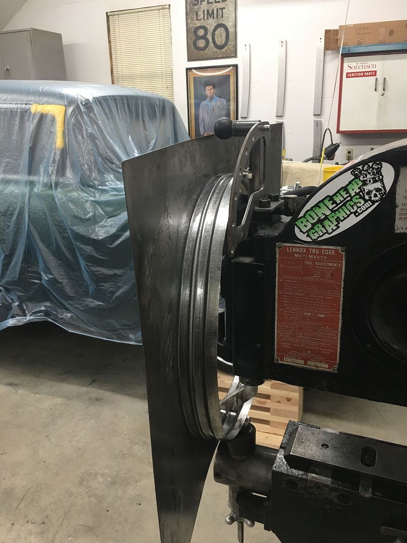
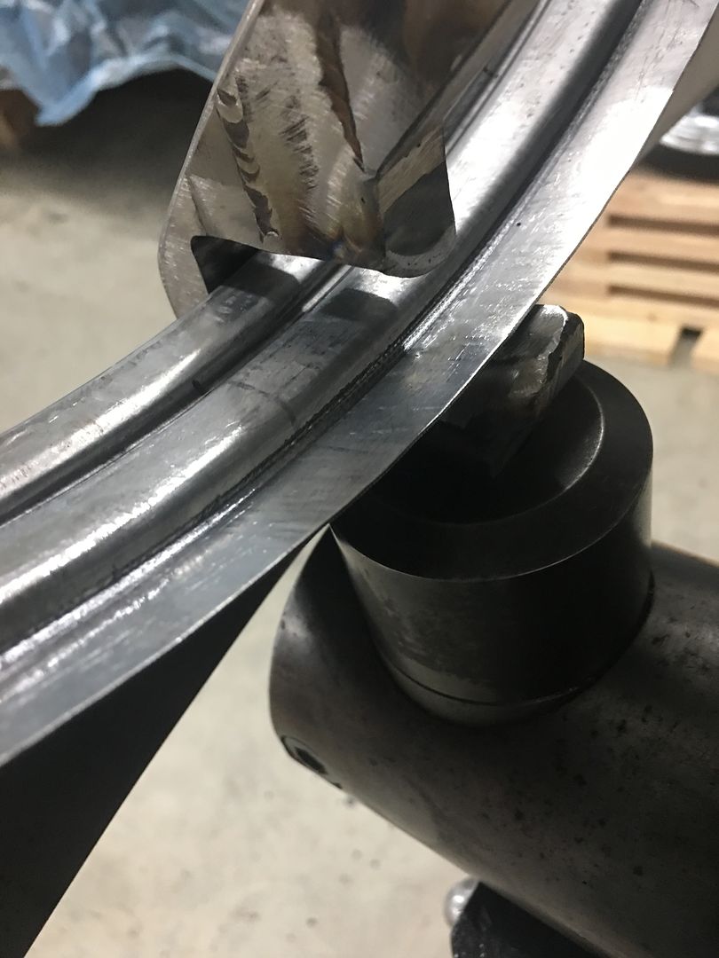
Next, adding the outer joggle for the wire. Our last mis-step at this stage was expecting a folded flange to perform as it did on a flat piece of metal.. But as a full circle with 1/2" of flange, it tends to resist any change in diameter, so our efforts to add the joggle (stretch outward) were met with catastrophic failure in the way of a split. This next attempt will leave that edge straight out instead of flanged, such that it will be more apt to move/stretch as we need it to.. Additionally, our dies will have a backstop built in and include two bead forming details. One will follow the center bead already installed, and with the back stop as part of the die, should correct any wiggle our bead roller may have added. Having both bead details added to the dies will also help to maintain correct spacing throughout. As these beading dies tend to pull material from either side, having multiple beads makes it more of a challenge to pull sufficient material for both and have enough for the bead height.. Adding one prior using the bead roller means we will only be "pulling" material for the one, for better results.
Our test sample shows the wrap for the wire straighter to the side, for less resistance to adding the offset.
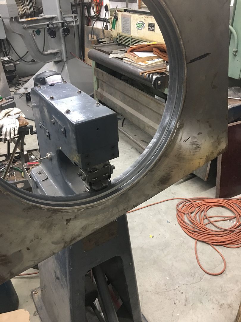
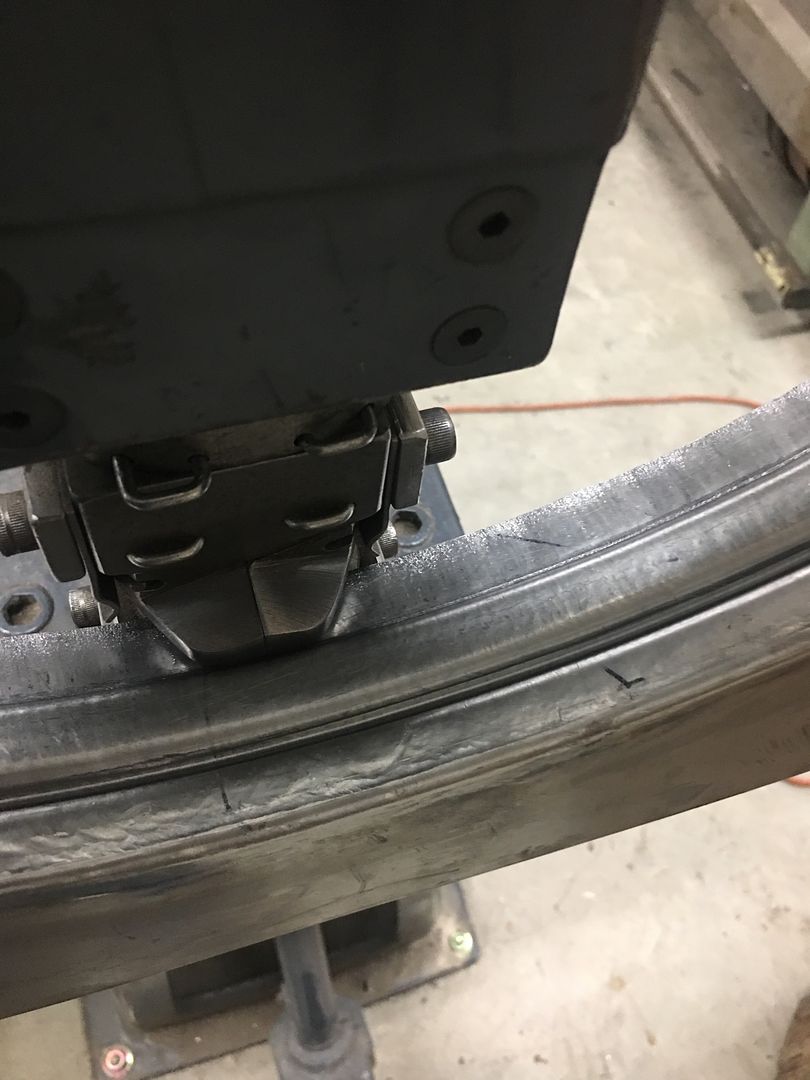
Shroud is then trimmed to size and run through the dies on the Lennox..
This did give us a slight potato chip shape of the panel, so the offset was stretched in the Erco..
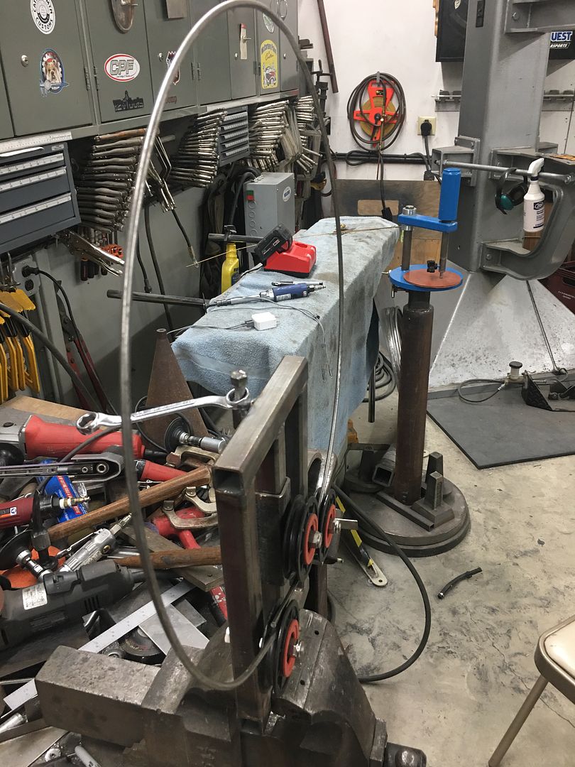
Our tubing straightener is used to make our 3/16 wire more concentric for an easier install..
Then the wire was test fit...
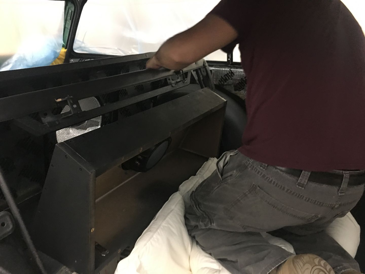
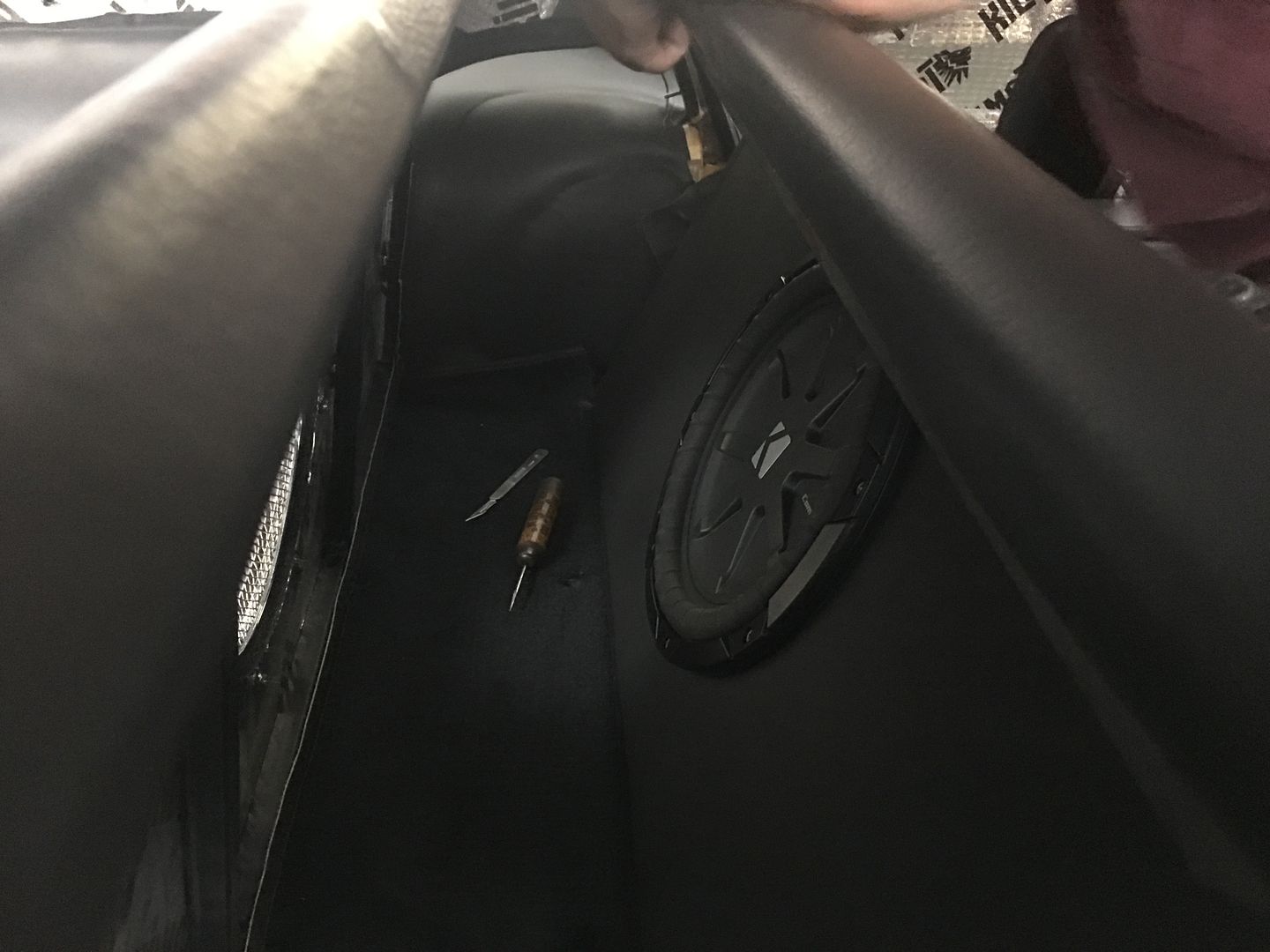
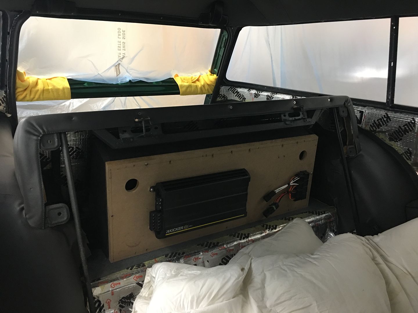
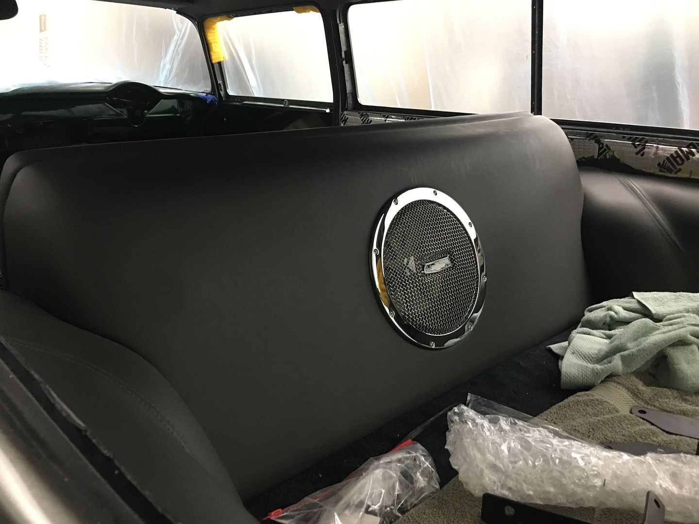
Mike got our interior assembly and wiring started, the rear tail light / fuel door actuator was installed, the sub box and amp installed, and our relays for the fuel door mounted adjacent to the amp, all tucked away behind the rear seat.
Robert
-
07-22-2021 05:24 AM #1635
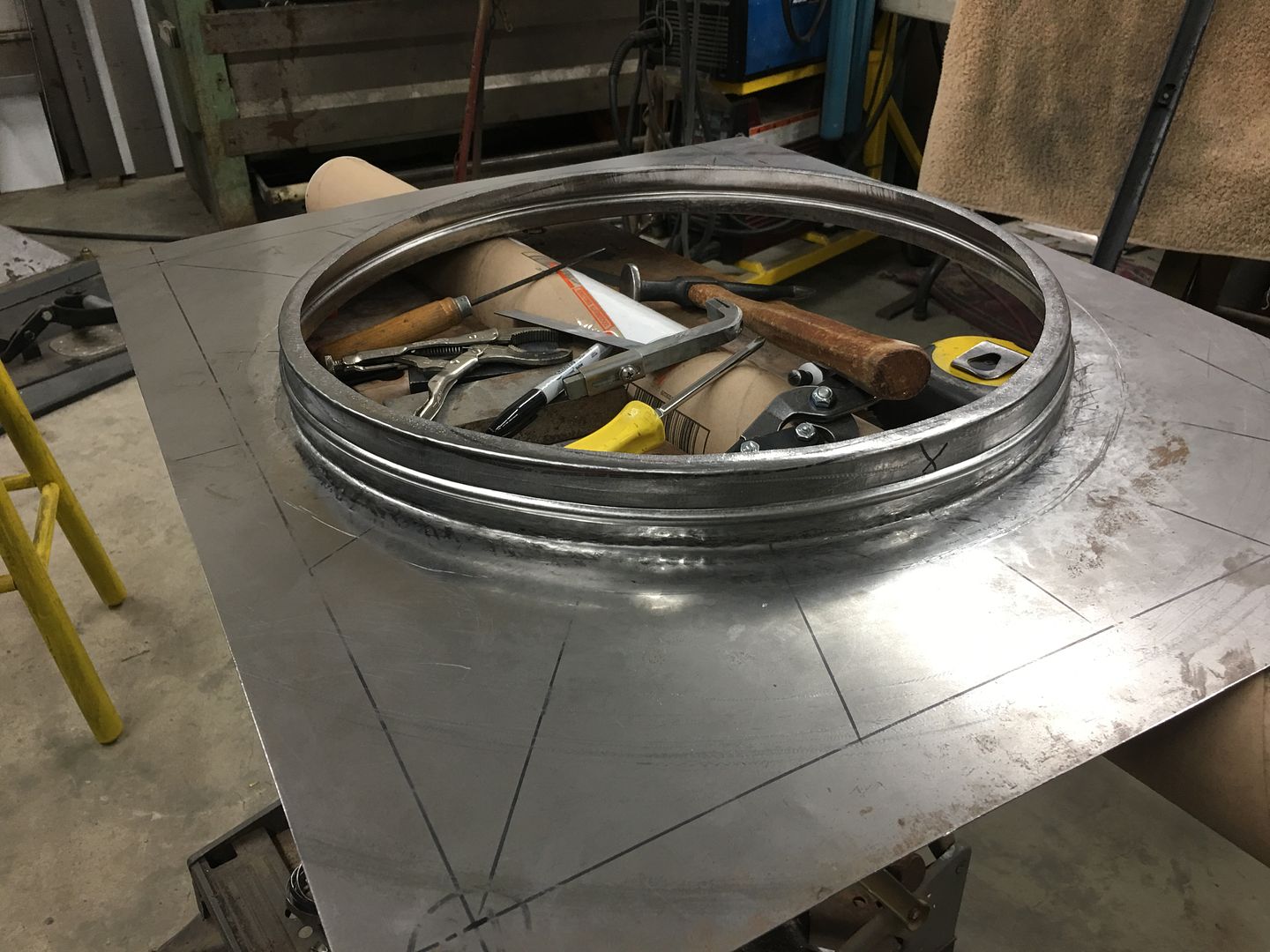
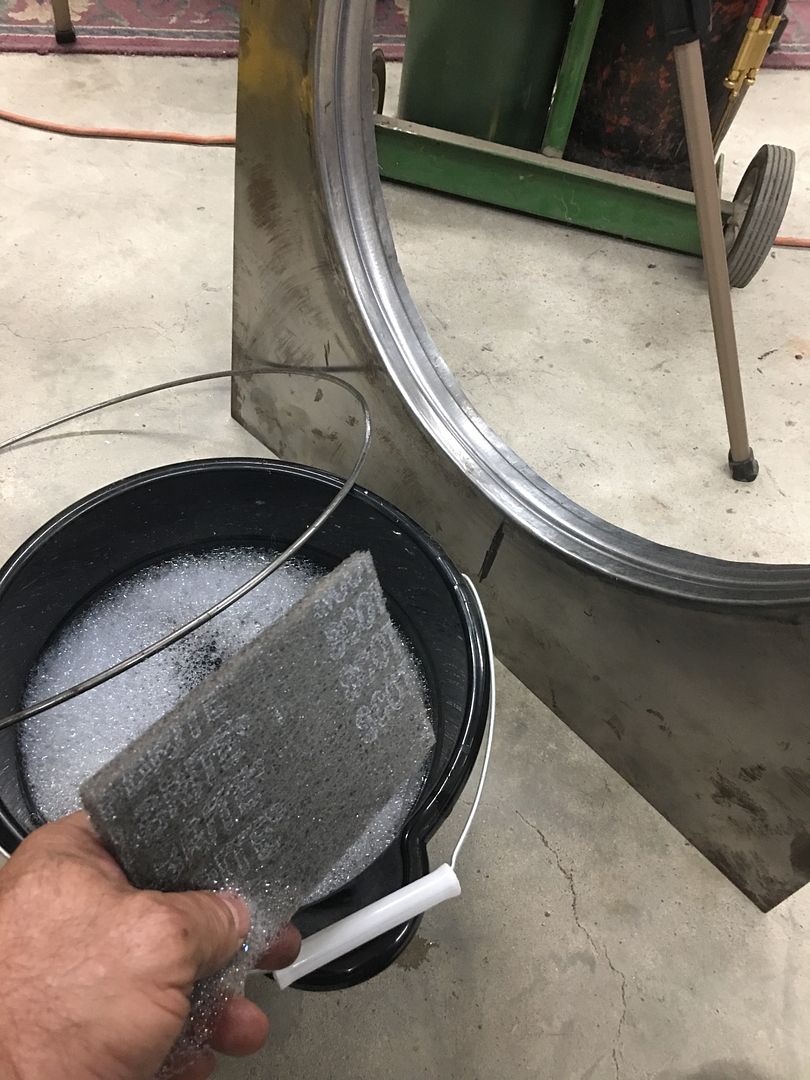
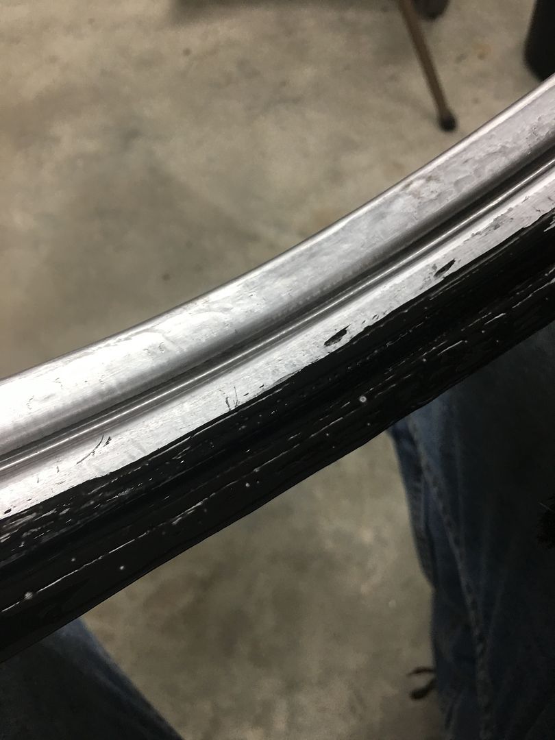
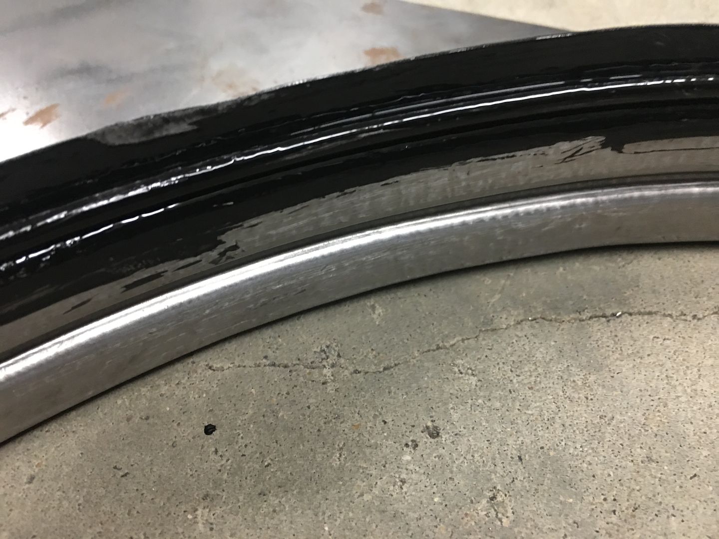
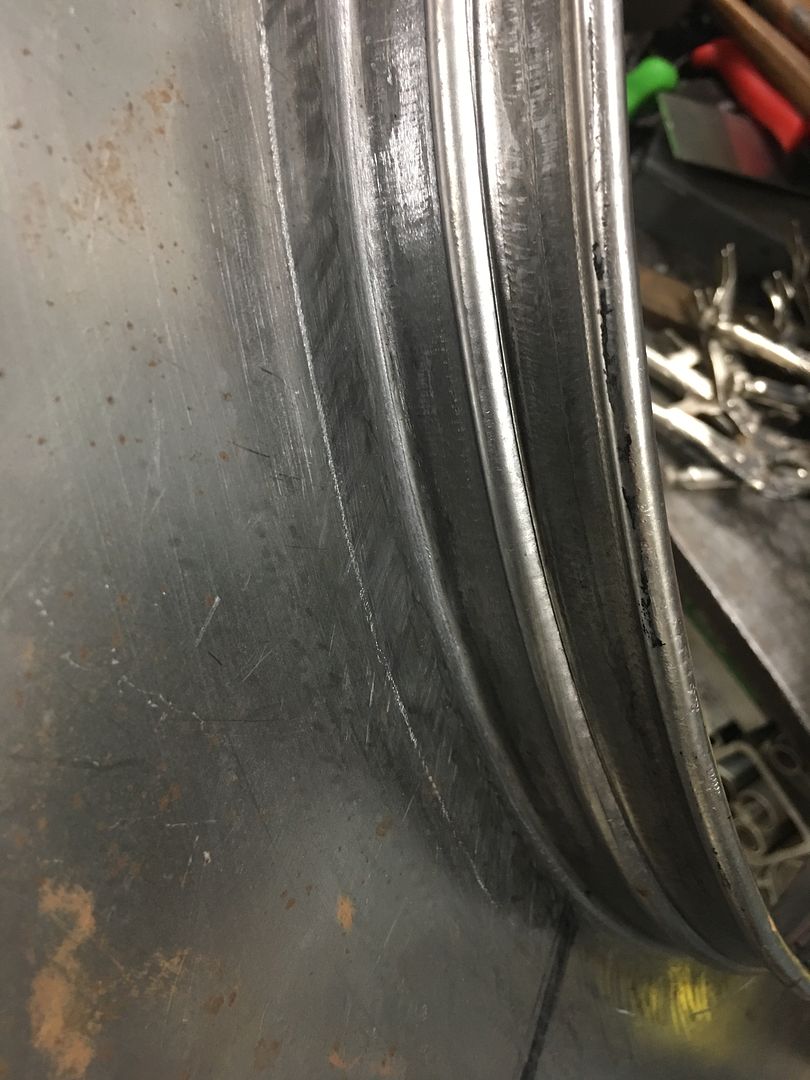
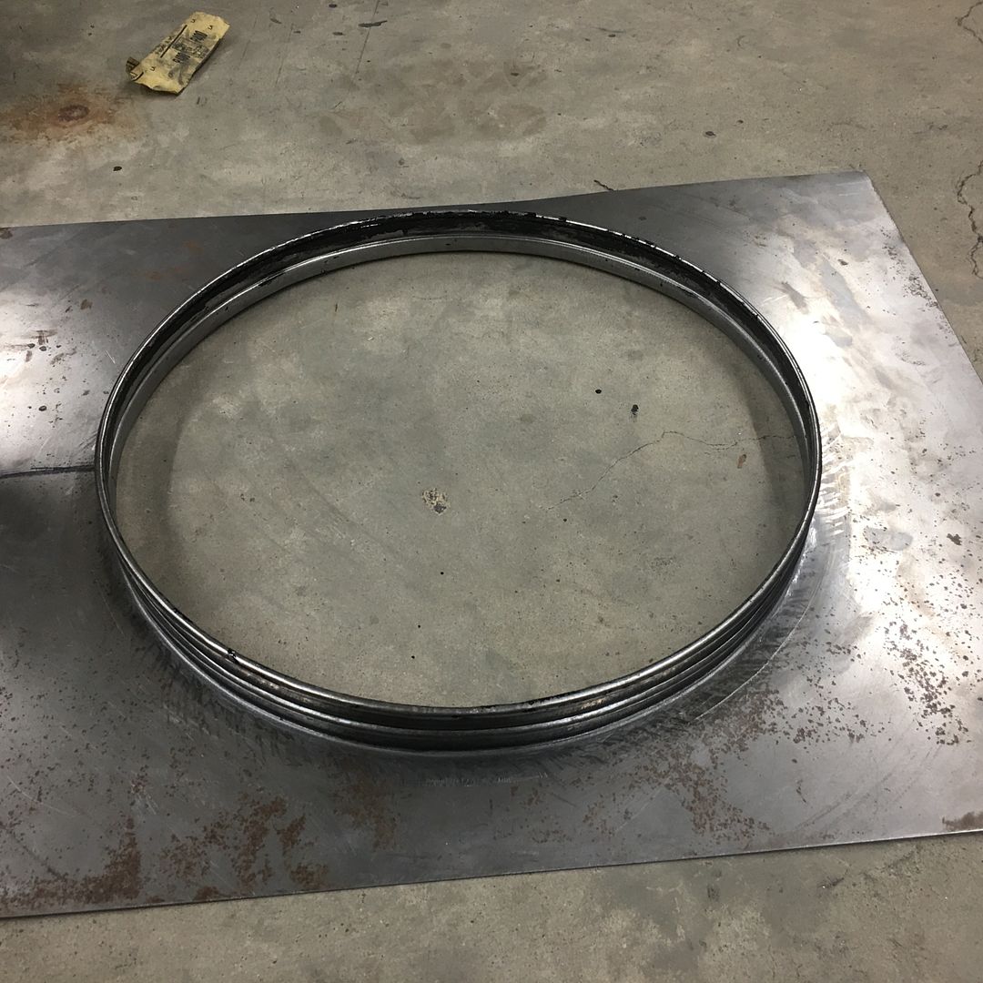
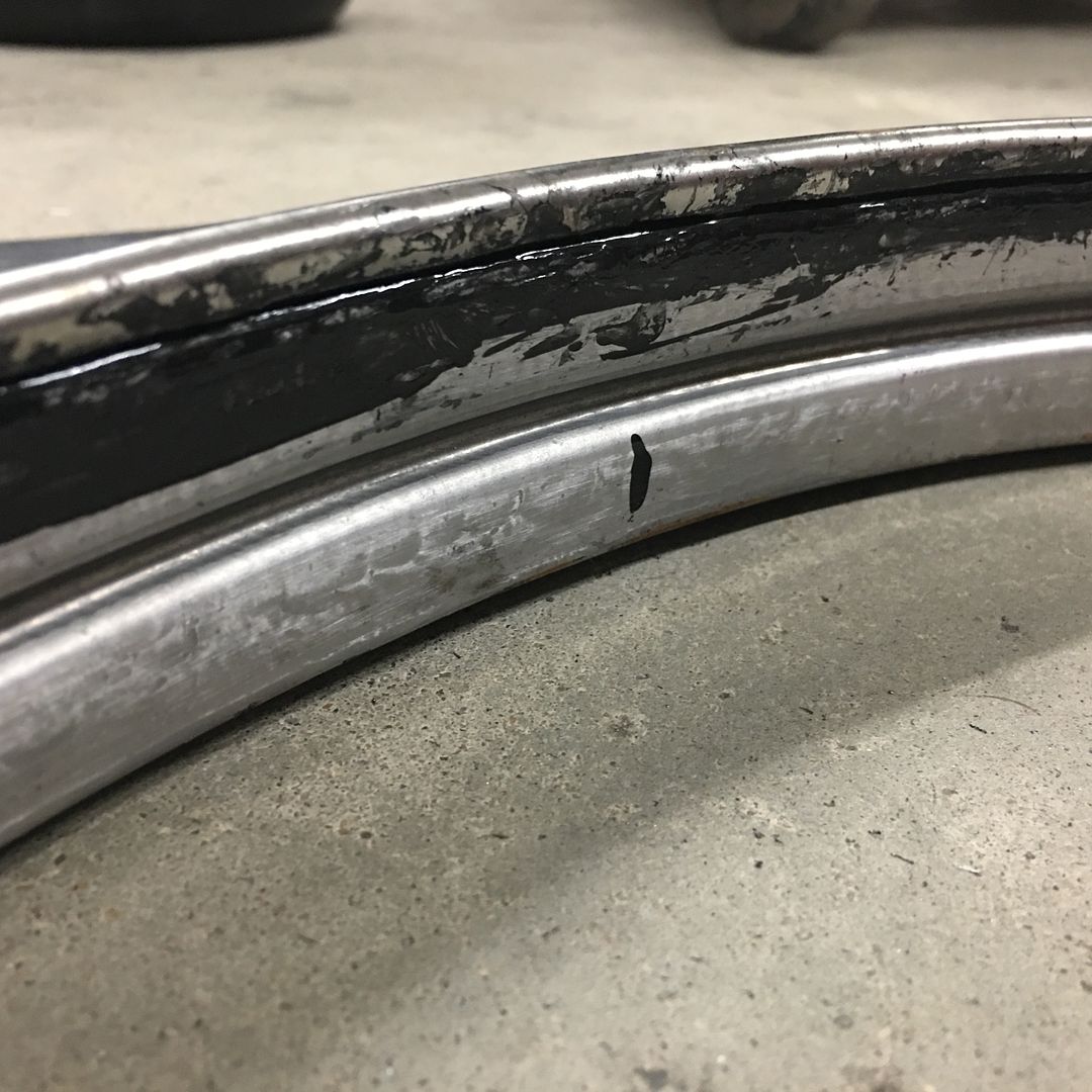
More progress on the fan shroud... Wire edging!! In order to stave off any rust issue as long as we can, I normally treat the wire channel to epoxy primer from the inside-out. So we used a scotchbrite pad and some Ivory liquid in warm water to remove any last remnants of the WD40 used for the last shaping effort on the Lennox.
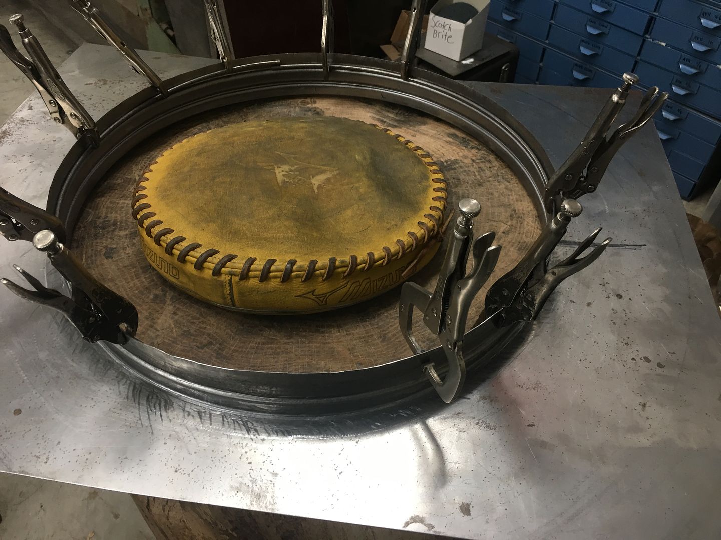
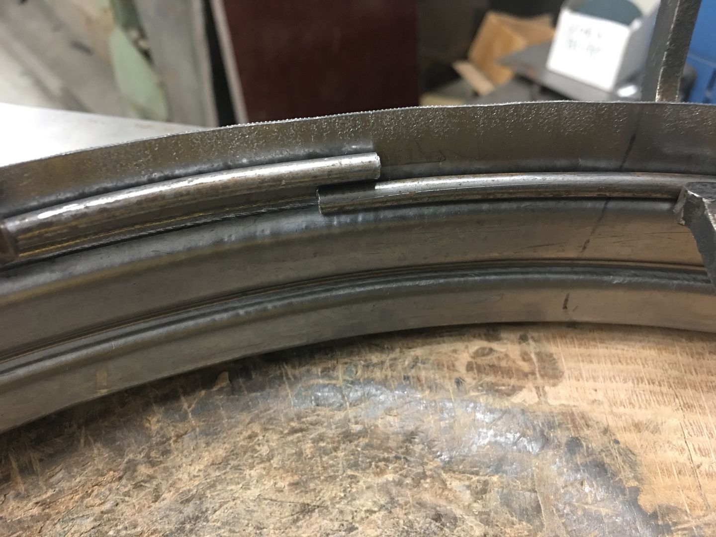
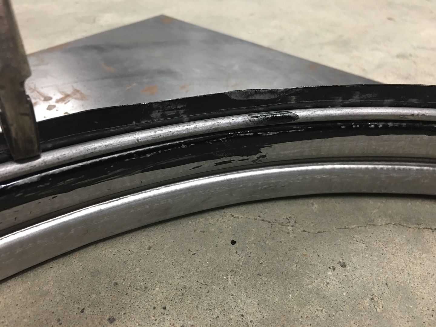
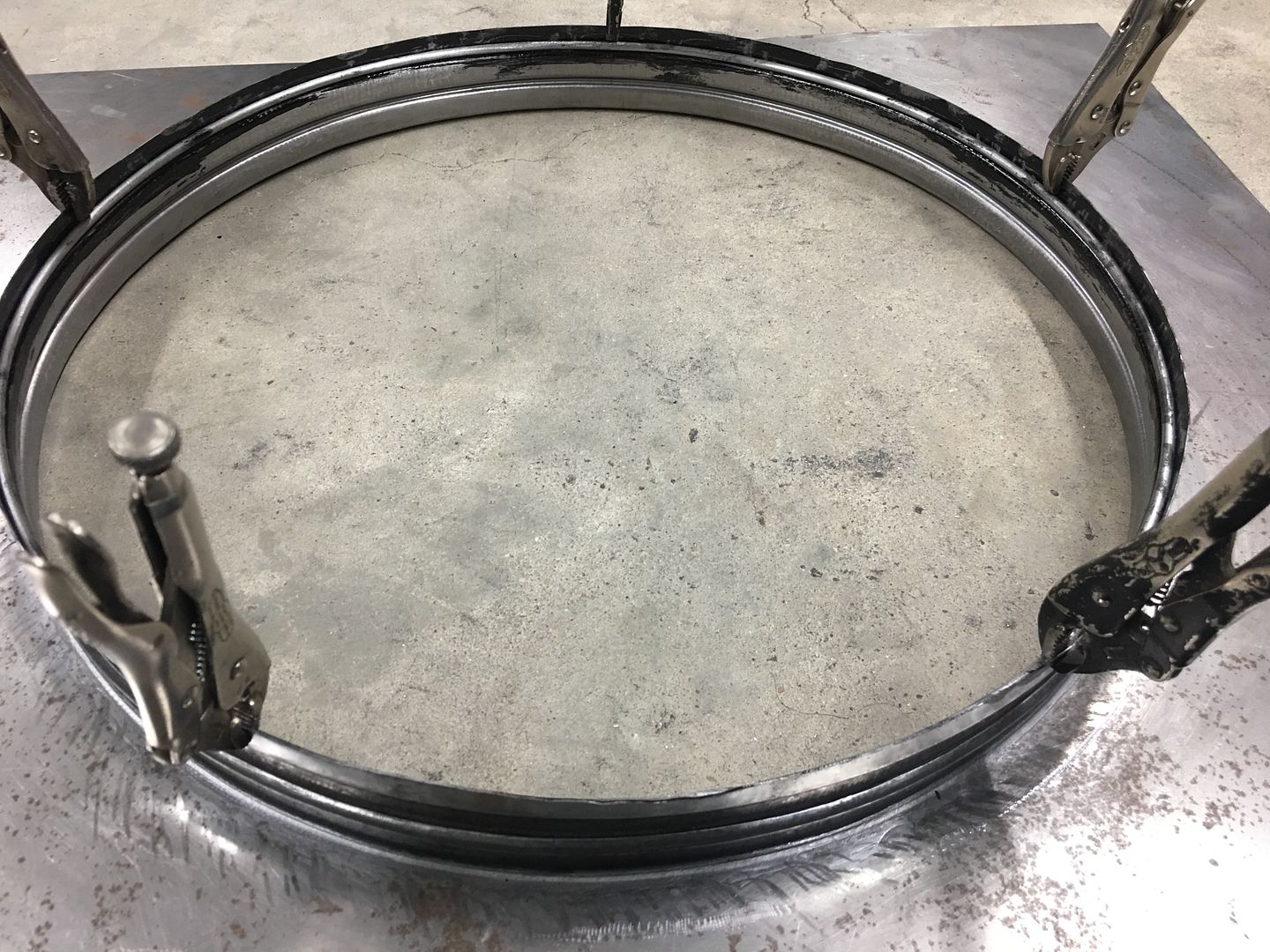
Our wire had been test fitted, sized, and tig welded together to form a continuous ring. This adds tremendous strength to the edge and helps to maintain a concentric circle. The wire was then cleaned as well. SPI epoxy was hand applied (acid brush) to the channel, the wire ring pressed in place (it was that tight) and then any bare spots on the ring epoxied as well..
The vise grips hold the wire snug to the bottom of the channel until the edge of the flange can be staked in place. Wire edging process, done using our cone anvil, various hammers, and a 90 durometer polyurethane pad for the final closure of the wrap..
https://www.youtube.com/watch?v=kHOjgRexM30
At the point we were hammering, the epoxy had set up approx 10-15 minutes, so it was not dry yet, but not running either. We'll let the epoxy set a couple days and get additional coats in the slight gap at the edge of the wrap in order to seal things well for rust prevention.
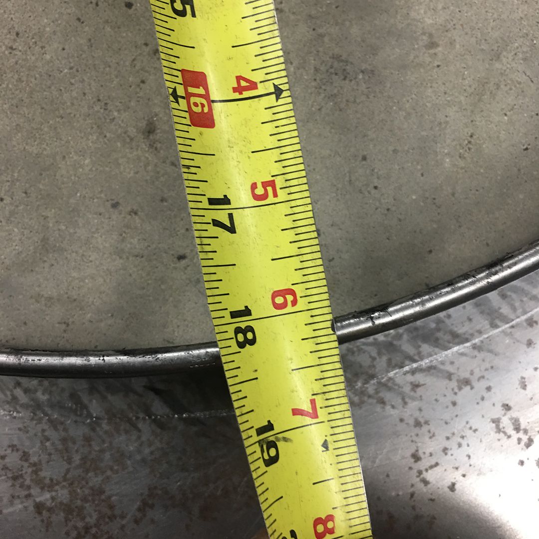
And our inside dimension worked out to what we were looking for, 18-1/8 diameter for our 17-1/4 fan blade.
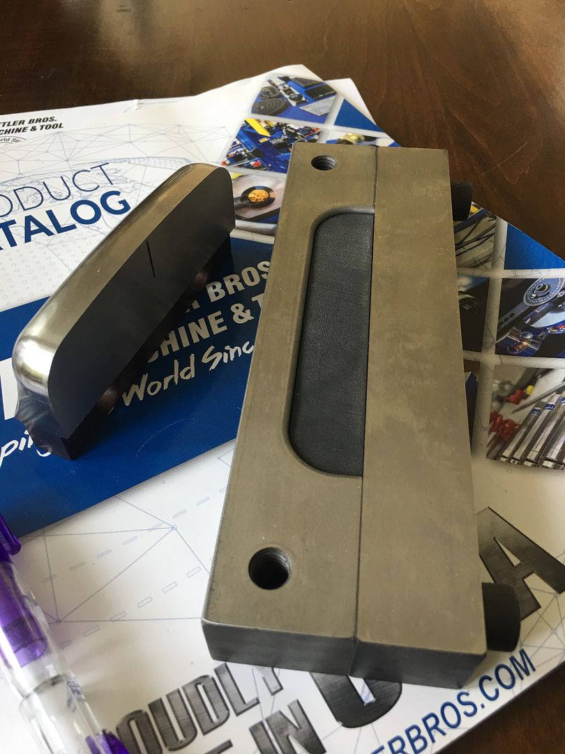
We also got another delivery, some 4" louver dies from Mittler Bros Machine and Tool for another job coming up. Will have to sneak it in here on some wagon parts as well.
Robert


 3390Likes

 LinkBack URL
 About LinkBacks
 Reply With Quote


Thanks for the happy birthday wishes, so far 50 feels a lot like 49 LOL
Happy Birthday 53Chevy5